Actually, looking at your dip switch, you may have the older design. This means you have a few more switches to play with:
Quote:
No of Cylinders............Switch1.....Switch 2......Switch 3
4...................................Off................Off................On
6...................................Off................On................On
8...................................On................Off................On
Quote:
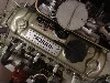
CAI Electronic Programmable Tachometer (EPT)
Introduction
The EPT can be programmed to accommodate 4, 6 or 8 cylinder engines and to accept inputs from Contact Breaker Ignition Systems and Electronic Ignition Systems.
IMPORTANT INFORMATION
* Only to be fitted to negative earth vehicles
* Disconnect your vehicle’s battery prior to installation
* Operating voltage is nominally 12V (11volts min 17volts max)
* The Tachometer complies with CE regulations regarding electromagnetic compatibility
Input Signals
The EPT can accept input signals from: -
1. The low tension side of the coil. On contact breaker or electronic ignition systems (except multispark and CDI systems)
2. Electronic Ignition Systems Dedicated tacho outputs. (Normally provided when the electronic system is multispark or CDI)
Programming Your EPT
1. Make sure that the battery is disconnected.
2. Make sure that your vehicle is negative earth.
3. Determine number of cylinders.
4. Determine input source, i.e. either contact breaker or electronic ignition.
5. Remove the black hole plug on the rear of the tachometer, by pressing it inwards, just above it’s centre, and then inserting a small coin or screwdriver into the edge of the plug.
6. Removing the plug will reveal 6 switches.
7. To programme the number of cylinders the switches should be set as follows:-
No of Cylinders Switch1 Switch 2 Switch 3
4 Off Off On
6 Off On On
8 On Off On
This is correct for vehicles with a single distributor. (The same number of spark lead outputs from the distributor as the number of cylinders in the engine) See note (A)
If your ignition system is multicoil and / or has no distributor
8.
For petrol engine applications switch 5 is always ON and switch 6 is always OFF
9. Please note, switch 4 adjusts for two types of electronic ignition, one of which generates it’s own voltage output for the tachometer (type b) and the other which requires the tachometer supply voltage (type a). If you do not know the type of ignition you have, set switch 4 experimentally to OFF. If this fails and the tacho does not work, switch to ON and try again.
10. To programme the input signal the switches should be set as follows:-
Input Signal Switch 4 Switch 5 Switch 6
Contact Breaker Off On Off
Electronic Ignition (type a) On On Off
Electronic Ignition (type b) Off On Off
Installation Of Your EPT
1. A hole is needed in the fascia panel, the diameter of which will depend upon the tachometer purchased, with sufficient clearance behind to accept the body of the tachometer.
2. Check that the battery is disconnected.
3. Wire the tachometer as follows:-
* Green Wire– Connect to power source via a 3 amp fuse
* Black Wire– connect to earth/ground
* Brown/Slate Wire– Not used in this application
* Red/White Wire–Power for the tachometer lamp, connect to a dash lighting power feed.
* White/Black Wire– For use with Electronic Ignitions which have a dedicated tacho output connection, otherwise not needed. Do not connect to the coil or distributor.
* Red/Blue Wire– For use when you have a contact breaker or electronic ignition without a dedicated tacho output. Connect to the low tension side of the coil. Otherwise not needed.
4. The tachometer can now be installed in the fascia panel hole, and clamped against the back of the panel using the fixing clamp, spring washers and knurled nuts supplied.
5. N.B. if the tachometer is totally inoperative at this point, when tested, and you have an electronic ignition system, it is well worth checking the settings of switches 4 and 5, and determining whether your system is type a or b. A simple way to check is to meter the voltage output from the electronic ignition, tachometer connection, if voltage is zero, then you have type a, any kind of voltage detected would indicate type b. Make sure that switches 4 and 5 are set according to the table in item 8 of the programming instructions.