Hi Everyone, its Tricky!!!
No, didnt stay at Indy Dion, would have loved to though - the women

, the cars

, did I mention the women
?? (Didnt get to take any photos of topless chicks, dammit!!)
However, I have been really busy being social - I have had two weddings in two weekends (friends, not my own). So not a great deal has been done to The Cat, but there has been some. I informed you avid readers last time that we were about to undertake the exhaust manifold (EM) fabrication for the new turbo, and I am glad to say its virtually finished. So, without further adue, here is the process as I see it.
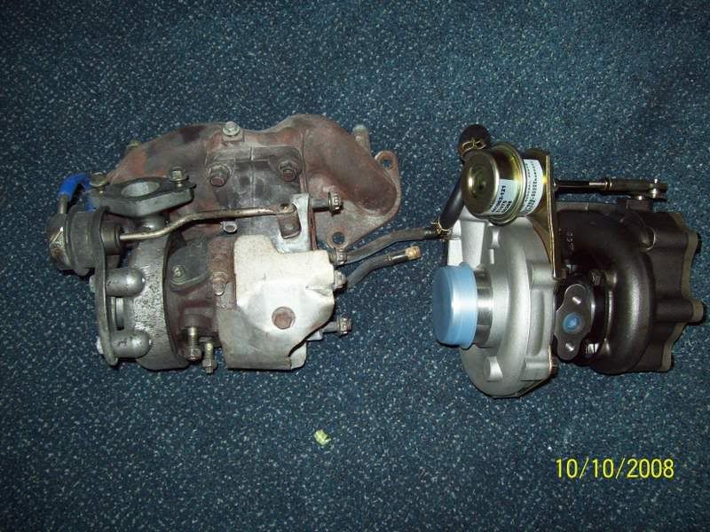
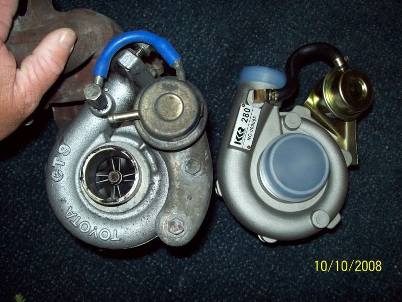
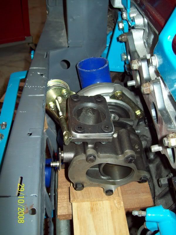
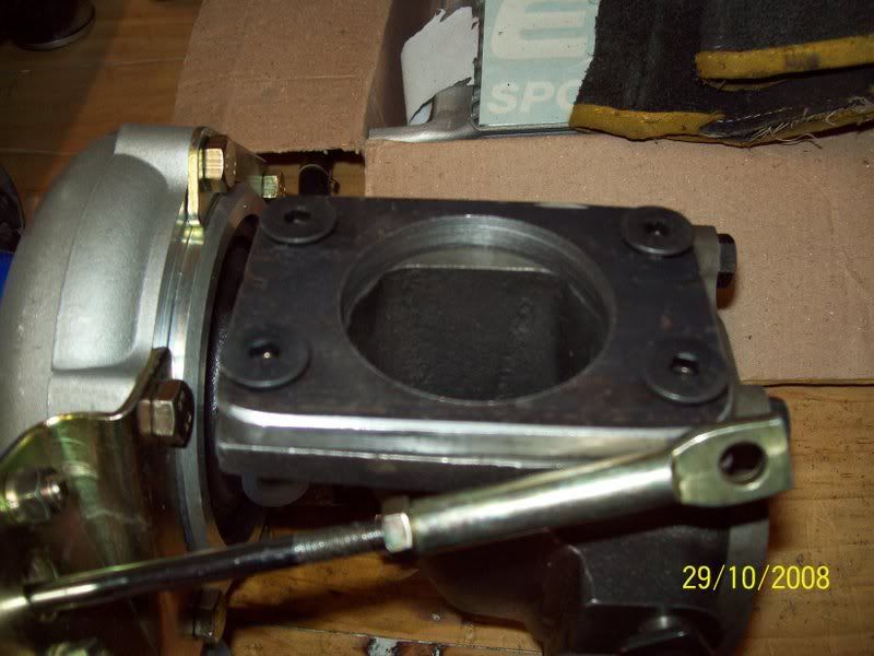
Okay, so the new turbo arrived, but how does it compare to the original CT9? Here is a comparison side-by-side. The KKR280 is slightly smaller than the TD04L, but it is larger than the standard CT9.
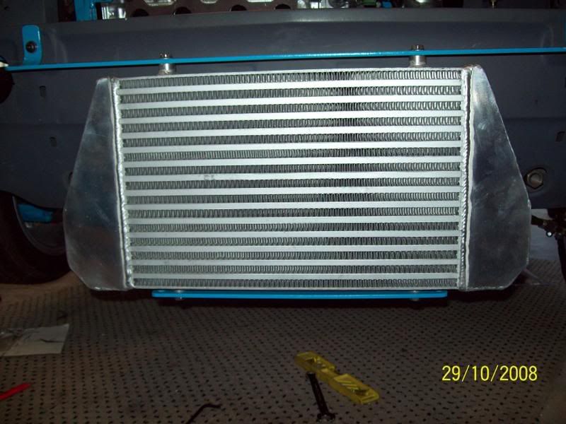
And shortly after the arrival of the new turbs, the new FMIC arrived. It is slightly smaller than the first one I bought, and not as high either. But it is slightly thicker. What does this mean, probably not much unless I was racing ten-tenths, but in terms of cooling efficiency it wont be as efficient as the older FMIC as radiator of heat energy. However, it did have the inlets and outlets in the right spot. Here it is mounted in position:
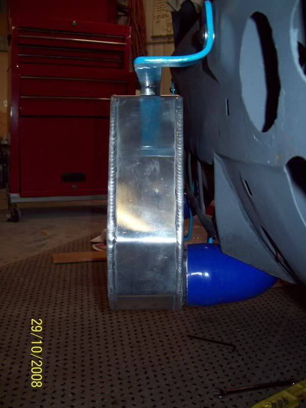
The new FMIC put the inlets and outlets in the proper position for the new turbs etc. As a matter-of-fact, I was really happy with where they ended up.
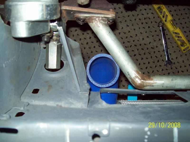
The inlet:
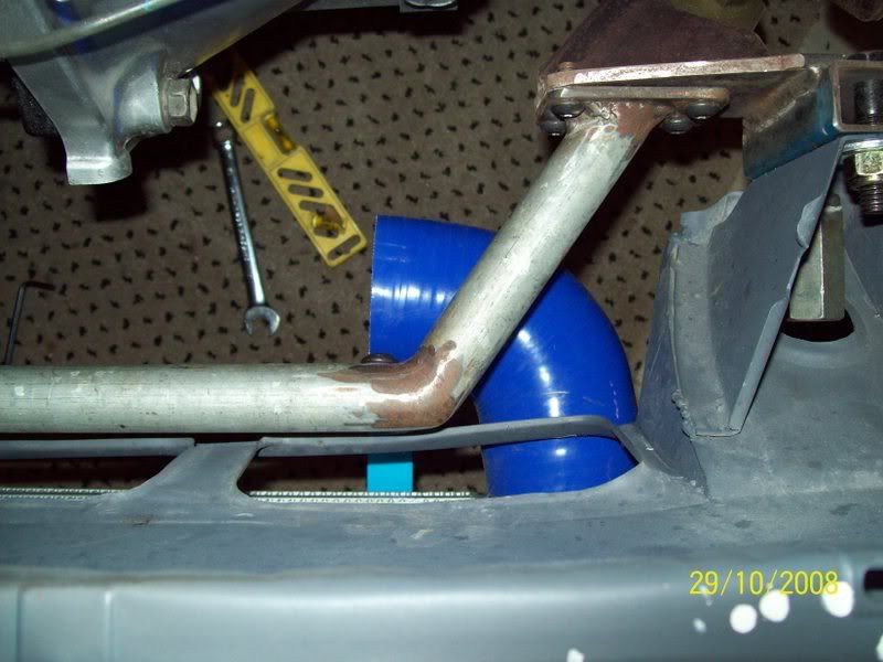
The outlet:
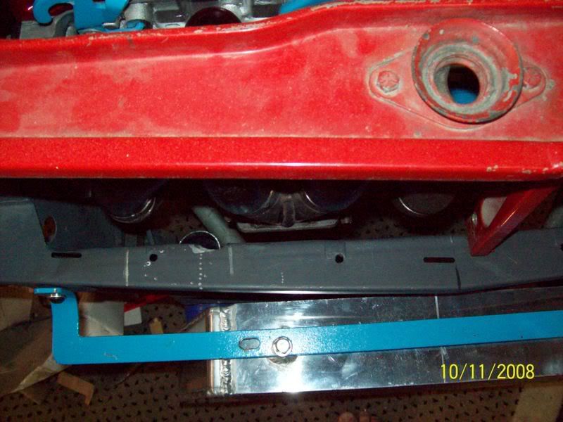
And here is the new KKR280 in its final position. Its a tight fit in there, but there is about 10mm clearance all around. I realised that I had to rotate the compressor housing to allow the right configuration, and this meant the actuator can mounting bracket will need to be altered.
And here is how the turbo compressor outlet lined up with the FMIC inlet - perfect!!
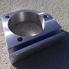
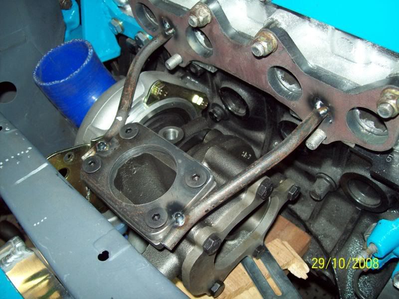
First step in the building of the EM was to make the flange for the turbine housing - fairly simple really as long as you have a largish holesaw (I already had the head manifold laser cut some time ago):
Then, once the flange is finished, its time to weld some stays to the flange while its on the turbo and in position, and this is what you should end up with. You dont want ANY movement here when you take take the flange off the head. Turbo in position:
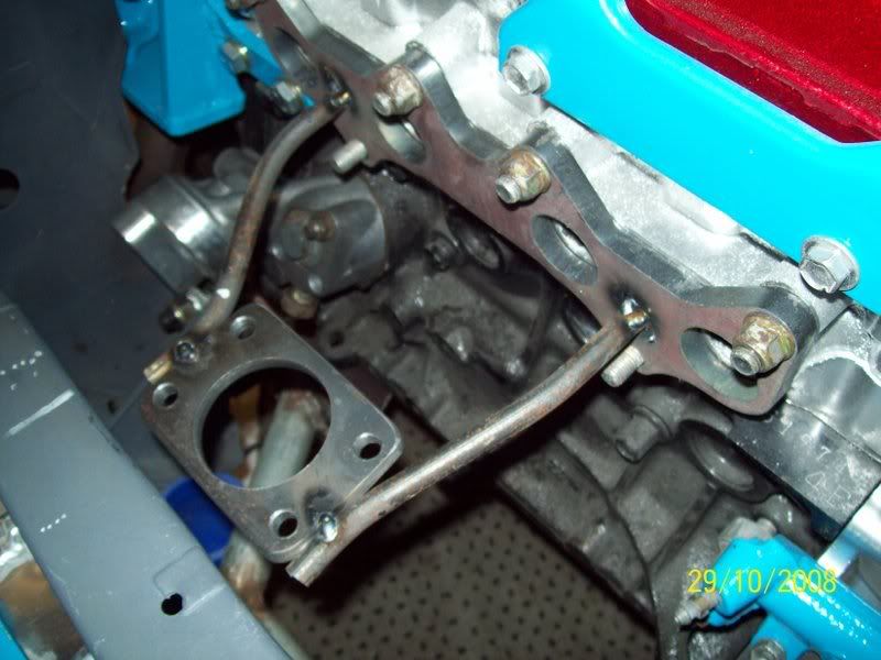
Without turbo:
The next part of the puzzle is to manufacture the collector. Ideally, the collector should be between 75mm and 100mm long, and the merge angle should be between 5 and 10 degrees. Mine ended up being 100mm long, and about 8 degrees in angle. They are a real pr!ck to make, and take a lot of time!
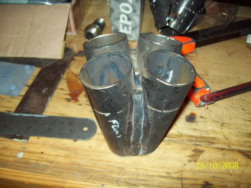
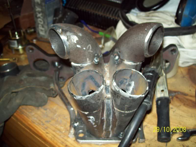
Now, tack the collector in position onto the turbine inlet flange, and start building your runners. I had the shape of the final shape of the EM firmly in my mind, so I just started. You may want to search the net and get an idea of the shape you want. My overiding design criteria was simplicity and tuned length, with aesthetics being third. Because the turbo did not sit dead centre to the exhaust ports, but off to one side, I knew the final shape wouldnt be symmetrical anyway. The start of runners 1 and 4:
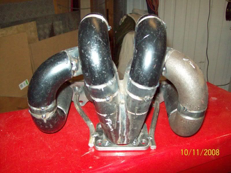
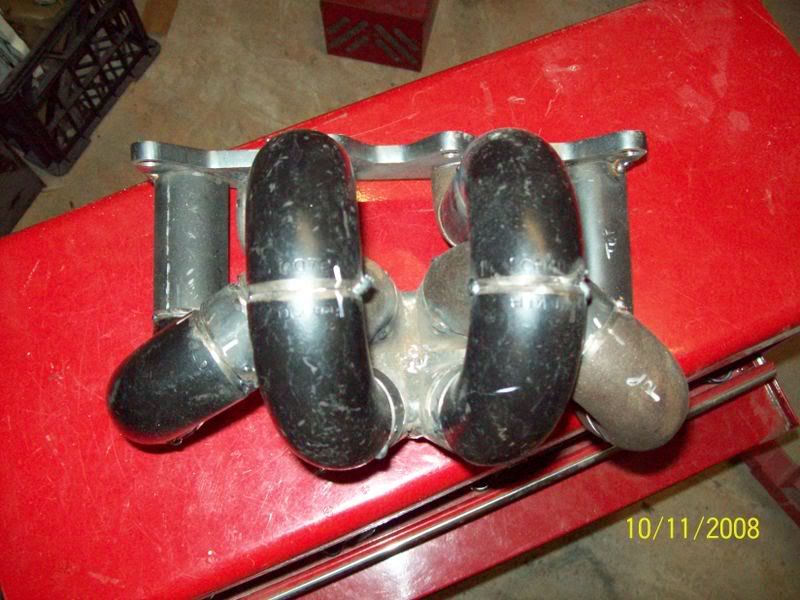
And this is the final product. Each runner is within 5mm of each other, so design critera number 2 was achieved. Final weight is bang on 6 kilo's, heavier than the cast original EM but it will outflow the original by a factor of about 3!!
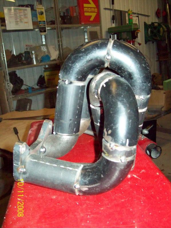
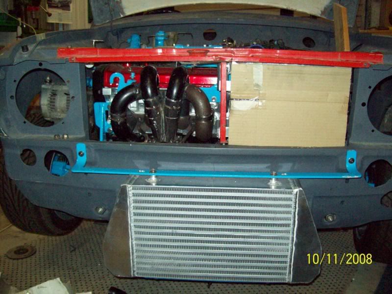
Here is the manifold test fit in place. I initially though it looked a bit large and bulbous, but on second thoughts, who gives a toss as long as it flowed!!
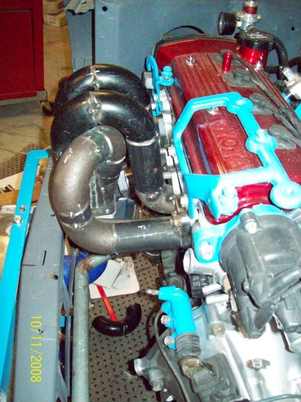
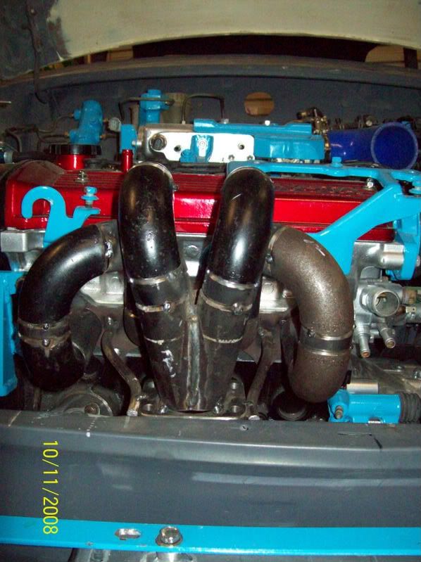
So, I wanted to get the new EM into perspective, so I started asembling the car and the other components in the engine bay to see if it would look like a horses ass, and much to my glee, it looked alright. Here it is with the slam panel back in place:
Notice how the EM follows the contours of the front of the car, so as not to foul the grill:
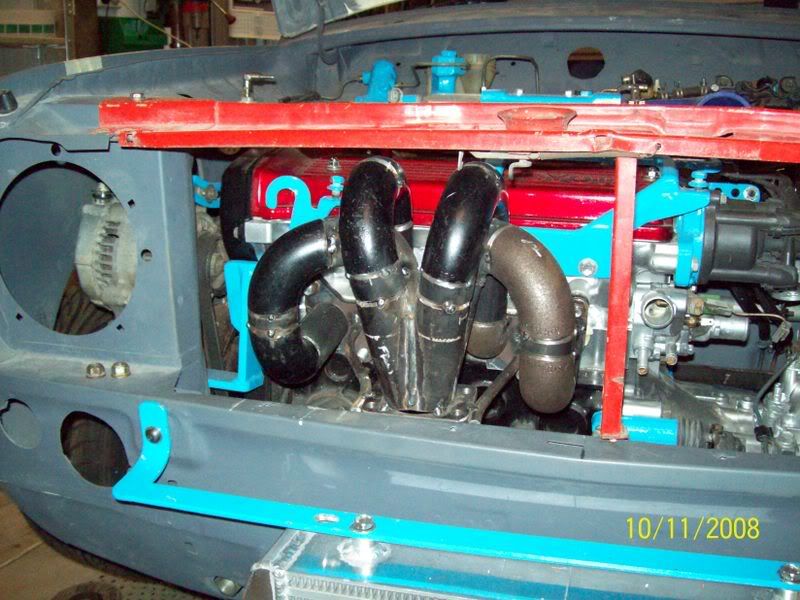
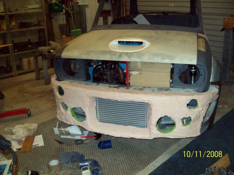
And with the radiator in position:
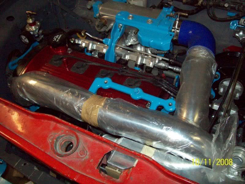
And with the charge pipes in position. The rear most pipe is the FMIC outlet that goes to the plenum. The front (top-most) pipe is the compressor inlet that goes from the carbon-fibre airbox where the old A-series radiator used to be located.
And then test fit for clearance with the bonnet down - all good!
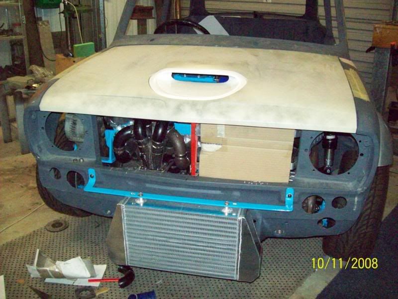
And a dummy fit of the front spoiler just to see how the spoiler would hide FMIC end-tanks and associated plumbing:
The only thing left to do for the EM is to fully weld it, and then send it off to get ceramic coated inside and out! So, now the next step is to TIG the charge pipes in place, mount the blow-off valve, and plumback it to the compresor inlet - next week perhaps.
Cheers,
Tricky