BEGINNING
Recently, with the spate of cars coming and going from QBR, most of which have been mates cars, and including my own, I have asked myself the question – “Why don’t I have a car trailer”, to which I answered “I don’t know, but we should at least investigate the possibilities”. I know that with Barbie’s backward and forward movement, it has cost Tony in the order of about $300 in towing fees, and he lives relatively close. Not to mention the added aggro of not being able to get the tilt tray when you wanted it and penalty rates for weekends etc. So, buying or building a QBR car trailer had real and apparent merit.
I drew up a list of desirable features that I wanted in a car trailer – after all, if one was going to buy a car trailer, one wanted it to be the best one could possibly afford; no use in doing things in half measures. The list of features went something like this:
o Tandem axles – so it had the carrying capacity I was looking for
o Electric brakes with handbrake – stopping a fully loaded trailer is essential
o Solid floor – makes it easier to walk on, and to put loose items on
o 200mm sides – again makes it easier to carry lose items without loosing them, also 200mm guarantees I can open a mini door while on the trailer
o Ramp racks – I didn’t want the ramps to be connected all the time, so they needed to have storage on the trailer
o Tailgate – again, so it would be able to carry loose stuff (like a half-cut) and not lose anything
o Tread-plate guards – sheet metal guards suck, cause they tend to bend under even the slightest load, like someone walking on them, and they soon look like crap
o Tread-plate panels – as above
o Winch post – why push when you can winch!
o Battery well – why manually winch when you can electric winch!
o Custom size – I wanted it to be able to carry Mini’s specifically, so a five metre tray was not needed, but be big enough to say, carry a mini and a half-cut in one go if I needed to
o Tyre rack – need somewhere to put the wet weather tyres and slicks out of the way
So, armed with this information, I visited the three largest trailer manufacturers in Brissie to get some prices for the trailer. Now, without mentioning any names, I was quietly shocked at the prices that I got back from the three biggies:
o Manufacturer one - $6,830 plus GST
o Manufacturer two - $7,250 plus GST
o Manufacturer three – no firm price but expect it to be ‘about $7k’
So, that sealed it – I was making my own, and this is how I went about it.
WHAT DO YOU NEED
You will need the following tools:
o MIG, TIG or Arc welder. Preferably a MIG as it will be the most efficient in terms of cost of wire and time taken
o Drill – a drill press wouldn’t go astray here as well
o Grinder – I use a 5” grinder – bigger motor than a 4” and not as ponderous and a 7”
o Tape Measure – obviously
o String line
o Pop rivet gun
o Square
o Level
o Various clamps - C-clamps, screw clamps, spring clamp etc
o Hammer, cold chisel, centre-punch
o Wire whee and flap-disc to suit your grinder
o Various sizes of drill bits, de-burrers, counter-sinking bits if you have them
o Spray gun and compressor (if you intend to paint yourself)
o Jig saw with fine-tooth metal blades
TIPS AND HINTS
o Measure everything twice (or even three times!), cut once
o Centre-punch every hole you intend to drill
o Clean-up as you go – this includes wire-wheeling the weld dags and splatter etc and sweeping the floor (try kneeling in metal swarf!)
o Use a level and square at every opportunity – don’t trust your eye
o Use the thin-kerf (1.2mm) cutting discs if you intend to use your grinder to cut with
o Flap-disc every weld or edge where fingers may go – nothing like getting a cut off a sharp edge!
o De-burr ever hole – I use a metal counter-sinking bit for this
o Use sharp markers, pens or pencils – continually sharpen your pencil too!
o Clamp everything before you tack weld it – saves it from moving
o Tack-weld everything before you fully weld it – on at least two or more faces or the weld will ‘pull it over’
o Always, always wear PPE (Personal Protective Equipment)
o Read the DOTARS requirements for trailers – there are rules which must be followed (if you need it, ask me!)
o Read through this thread first, before starting, as you may need some clarifications at important steps
o File all cut edges of sheet metal – it only takes a slight dag to give you a decent cut!
DESIGN
The next step was to draw up a set of plans for the trailer with exactly what I wanted – if I was going to build it, it was going to be customised to the nth degree.
o The intended use dictated the size – tray dimensions of 3300 x 1800mm. This meant that with a Mini sedan onboard, I still had 150mm space back and front and about 250mm space down the sides – enough space to walk around the car without falling over or getting off the tray bed. Also, with the Mini hard up against the front, I had enough room for a front-cut too
o The sides as stated, would be no more than 200mm high so the doors could be opened once loaded.
o The ramps and tailgate had to be detachable with a quick-release system that would enable fast changes between the two – that meant no tools to be involved.
o The tyre rack had to be able to carry one full set (that’s four tyres) of either wets or slicks. That gave me 2 full sets, one on the car, one on the rack.
o The electric winch had to be removable – I didn’t want to leave it permanently connected to the trailer, exposed to the elements, or worse, theft.
o Mag wheels to save weight, standard size so replacement tyres would be cheap, but a common PCD, so they were cheap and easy to find
o With four wheels on the ground, I wanted 50% redundancy in terms of spares, so two spare wheels had to be carried
o Storage space and lots of it. With the need to carry straps, chains protectors, jack, wheel brace, rags, winch and controller etc, storage space was a premium requirement.
So, the plans took me about a week and half to draw up – by hand, as it would have taken me longer with CAD or SolidWorks as I am not that proficient. Once the plans were finalised, I took a cut-sheet off the plans. A cut sheet is a list of materials, quantities and sizes for the project. With this in hand, it was down to the local metal merchant to get the steel quoted. I soon realised that no-one does 200mm side panels, so I had to design my own side panels. I decided on 1.6mm gal-sheet for this, a standard size. I made the profile 50mm deep to match the frame, and to give it maximum strength.
Now with the design, it is personalised towards the way I wanted the trailer to be set up, and to ensure that function was never compromised by form. And this showed up in the design.
Note:
The design can be changed quite easily, so I have come up with the following identifiers to help you customise your trailer to suit your needs. It is also imperative that you read through the entire thread so you can identify the changes you want to make, before you start.
Note (BLUE) – indicates a design input that can be customised. These will appear through out the thread as an opportunity to change the design to suit your needs.
And with changes in design, came changes in cost, or the opportunity to save money during the build by substitution, inclusion or deletion.
Note (RED) – indicates an opportunity during construction whereby money can be saved by substitution, inclusion or deletion of design or materials. These will appear throughout the thread.
Note:
The trailer plans and cut-sheet are freely available to anyone who requests them FOC.
MATERIALS:
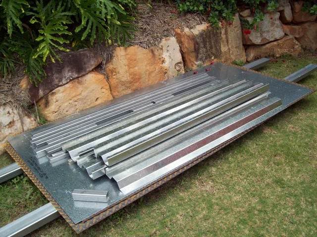
The steel was cut to size by the merchant, and delivered to home. This is how it turned up, in a bit of a flat pack. The main chassis will be 50x50mm Duragal RHS with 2.4mm wall thickness – easily strong enough for our needs. The sides are 1.6mm gal-sheet. The floor, guards and all in-fill panels are 2.1mm tread plate. The rack frame is made from 30x30 Duragal RHS in 2.0mm wall thickness, and the rack sides are again 1.6mm gal-sheet. With everything cut to size, we can now start the construction of the trailer without any delays. So let’s begin:
This is how the steel was delivered, doesnt look like much:
 THE CHASSIS
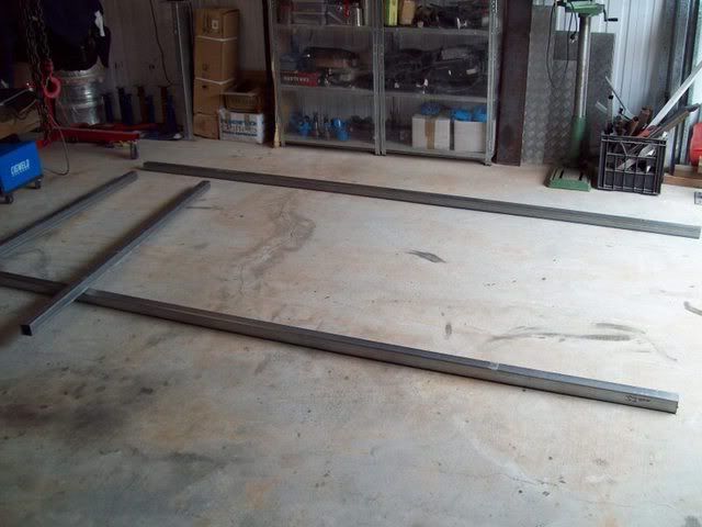
Begin by tacking up the chassis. The main rails are 3300 long, and the cross rails are 1800 long. There are 8 cross rails, at spacings of 412mm between centres. Measure along each main rail the spacing distances and mark them off. This will help you keep the spacing right and the cross rails square to the main rails. If you change the dimensions, make sure you keep the spacing between rails at no more that 450mm maximum.
Chassis being laid out on the floor:
 Note: The dimensions of the trailer was made to my specifications, you can either lengthen or shorten the tray to your desired length/width.
Note: Remember, the longer the tray, the more cross rails, which ultimately means more cost.
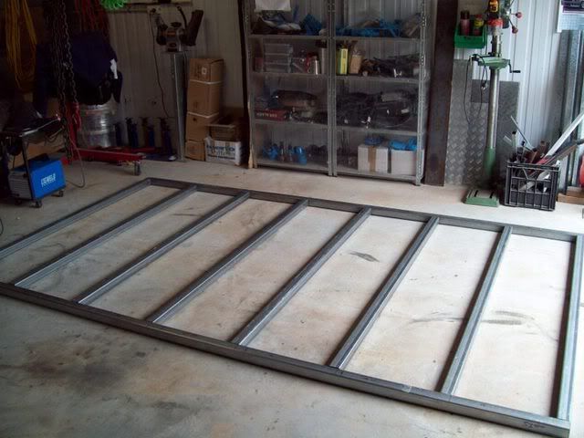
Ensure that before tacking the chassis together, the cross rails and main rails are level and square with each other. Before and after the cross-rails are all tacked together, check diagonal corners for overall squareness. With my length of 3300mm, I aimed for ±5mm in the diagonals and obtained about 2mm. Tack all cross rails on at least three faces to stop them moving when they are fully welded.
The chassis just before tacking:
Chassis tacked up and square, ready for welding:
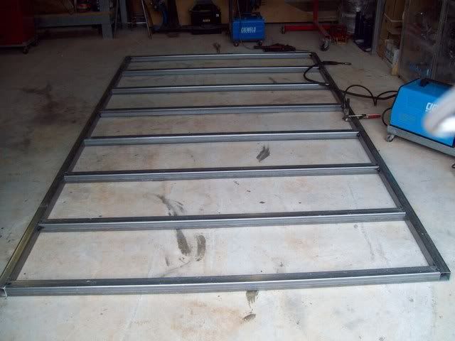
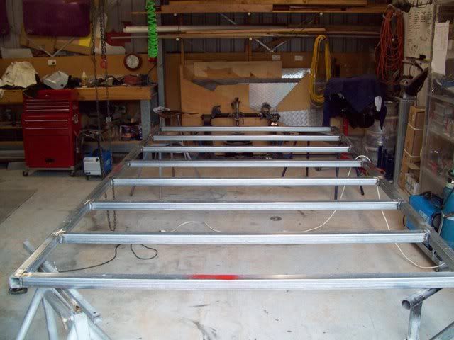
Now that the chassis is square, plumb, level and tacked up, proceed to fully weld it. I welded the upper face first on all rails. Once this was done, I stood the frame up on its side and welded all the junctions on that frame rail. Then, I flipped the frame over and welded all the junctions on the other main rail. Finally, with this complete, I laid the frame flat again with the un-welded side up, and welded that junction. Now you have cross rail to frame rail junctions that are fully welded on all four sides, and all none of them were overheads!
Now the frame is all square and fully welded, place the frame on some stands – no need to work at ground level when you can work at waist height! A handy hint here – level the trailer on the stands – helps when you level everything else as it will be perfectly level with the chassis as well. Its now time to add the 50 x 50mm x 200mm corner posts. Begin by grinding down any high welds that sit proud of the upper face at the four frame corners. Sit the corner posts in their positions, making sure they are plumb and square, and flush with all outside faces, and then tack them on. Once you are happy with the placement, fully weld on all four sides.
Chassis fully welded and up on stands (if you dont have some sturdy metal stands, make some):
 SIDES:
Now its time to add the sides. My sides came as six pieces, one front panel at 1800mm wide, one rear tailgate panel (slightly different profile to the sides – see drawings) at 1800mm wide, and 4 side panels at 1600mm wide. The reason I got four sides is that the pan brake that was used to bend up the profile could not do 3200mm wide (3200mm, where does that come from? I hear you ask. Add two corner posts at 50mm plus the two side sheets at 1600mm and you have 3300mm, or the full tray length!). Once you have tacked up one panel on one side, its time to add the other half of that same side. Once again, tack it to the corner post and the main rail. Ensure that the junction between the two side panels is near perfect. During the trial fit with the second panel, mine was about 3mm too long. Once trimmed it was fine.
Note: If your tray length is less than 3300, it may be possible to bend up side panels in one length.
My sides came in two pieces because the brake couldnt bend more than 3000mm. Here is the first part of side 1 tacked:
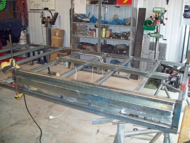
Now tack together the two side panels where they join, ensuring that the junction is nice and flat and smooth on all faces, especially the top. Mine hade a bit of a curve over the length of the panel, so I couldn’t get this face perfect, no matter how hard I tried. Once the side panels are all tacked up along the bottom, up the corner posts and where they butt each other, go ahead and seam weld them to the corner posts, the main rails, and to each other.
At the junction of the two panels, I welded a piece of 75 x 250 x 5mm flat bar joining plate to the outside face of the join. This gave the join some stability, and also reinforced the panel over its entire length as the flat bar was welded to the main rail as well
Side 1 complete, with stiffener in place, and fully seam welded:
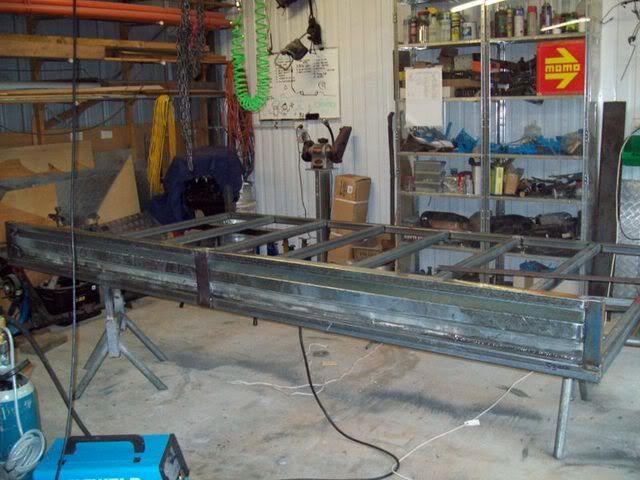
Sides welded to corner post:
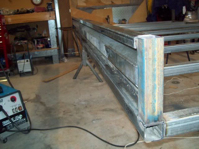
Side 2:
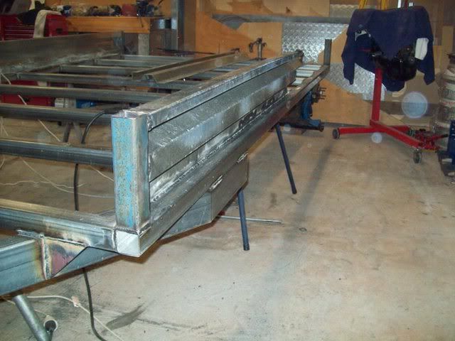
Once you have finished with the joining plate, move onto the front panel, and the other two side panels. The front panel being in one piece does not need a joining plate to strengthen it over its (only) 1800mm length. You now have a tray that has three sides, and its starting to look like a trailer.
Front panel:
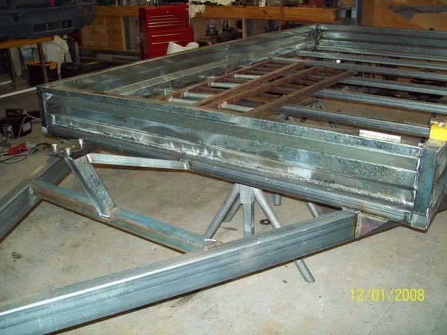 Note: A lot of dedicated car trailers do not have fully enclosed ‘sides’ per se, I chose to put sides on mine as to me it makes it more flexible and useable.
Note: By eliminating the sides, considerable cost and time savings can be made
DRAWBAR:
The drawbar consists of two equal pieces of 100 x 50 x 3mm Duragal RHS, and some ‘capping’ plates of 5mm or 6mm flat bar. I chose to make the length of my drawbar, from the front of the trailer, to the end of the drawbar (not including the coupling) 1200mm long. That means that the two sides of the drawbar are 1900mm long, as there is 700mm of drawbar under the trailer.
Note: Drawbar length is an individual thing. I like my drawbars long as the longer the drawbar, the slower the steering of the trailer (we all know the aggravation of reversing a trailer that seems to snap left to right with the slightest steering input – this is a result of short drawbars! Some people like to keep the drawbar relatively compact, especially if the trailer tray is fairly long).
Some simple trigonometry will allow you to ascertain what angle to make to cut in the RHS to allow the drawbar sides to come together perfectly. Mine worked out to be 450mm of straight drawbar parallel with the main rails, then a cut of about 15 degrees, 250mm of converging drawbar still under the trailer, and then 1200mm or converging drawbar after it clears the front of the trailer. See the picture for clarification. By running a string line down the exact centre of the trailer, it allowed me to cut on one side at a time with a certain amount of accuracy. I then tacked the first side to the frame only along the parallel part of the main frame, this left the rest of the drawbar to swing backwards and forwards if you like, to ensure a neat fit with the other side. Cut the front of the drawbar side one along the string line at your desired length.
Drawbar side 1 clamped in place ready to be tacked:
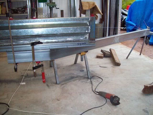
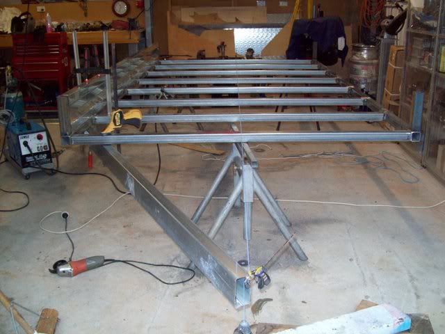
Now do the same with side two, tack only along the parallel with main rail face. Bring the two sides of the drawbar at the front together, and mate them up which will dictate where the cut on the second drawbar will be. Tack them together at the front, making sure that the drawbar join runs perfectly along the centre line (string line) of the trailer, or else it will be towed a little off centre. Once you have this front part tacked, square cut the very front face of the drawbar parallel with the front of the trailer tray. Now, go ahead and fully weld the drawbar to the trailer at all intersection points.
Side two done identically to side 1 - use a string line!:
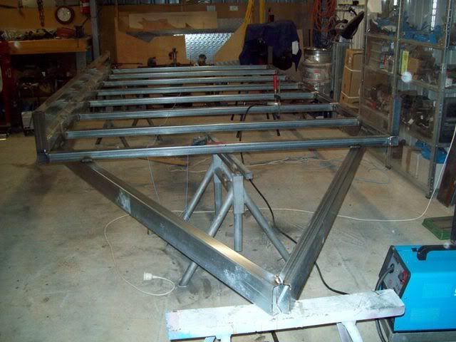
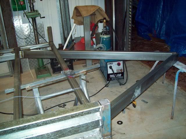
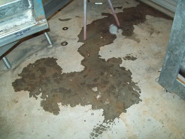
It was raining so hard in Brissie, that the water flooded in under thw workshop roller door!
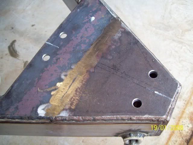
With the drawbar fully welded together and to the frame, its time to plate the front of the drawbar to ensure it stays together under any twisting loads, and to enable mounting of the coupling. My coupling is fairly long, as it has an integral hand brake in the design, this forced me to plate along the drawbar for a distance of 300mm using two plates. I then plated underneath (what I call the ‘skid plate’ if the trailer ever comes off the tow-ball, and also along the front face. I used 6mm mild steel plate for this.
Front plate:
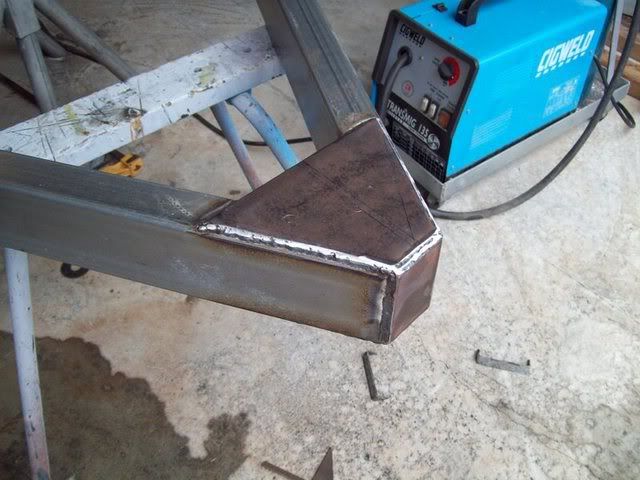
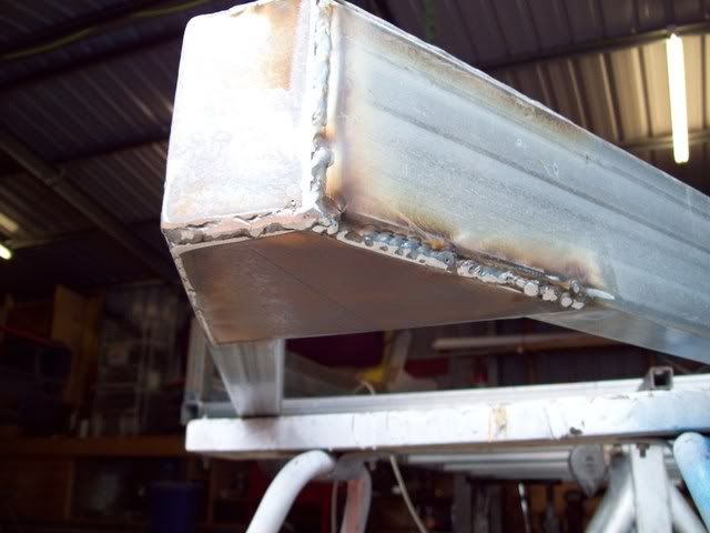
The next step for the drawbar is to weld some triangular gussets between the draw bar and front cross rail where they intersect to stop the drawbar rails twisting against the cross rail. Simply cut one piece of 6mm plate 100mm x 100mm (I made mine 120mm x 100mm to give a little extra length along the cross rail) and then cut across the two diagonal corners – this will give you two identical triangle pieces. Weld these to the outside of the drawbar to cross rail junction, parallel to the cross rail. The picture explains the positioning best. Weld all meeting edges on both sides.
Gussets:
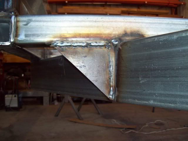
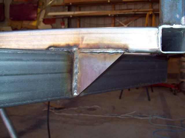
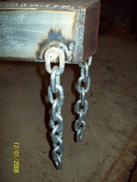
Next job relating to the drawbar is to weld a cross rail between the two drawbar pieces so you can mount your winch post. Here is used some 50mm x 50mm x 4mm for the job. I simply marked out where I wanted the cross rail to sit, in this case it was midway along the drawbar free length, or 600mm from the front of the trailer. Mark your mounting points on the draw bar, making sure they are equal distance, then align the cross-piece under neath the drawbar with the marks, and then scribe the cutting angles using the drawbar pieces as a guide – simple! Now cut the piece and weld it in, ensuring that it is level and parallel with the front of the trailer. The winch post up-stand can now be measured, cut and welded into place also. Mark the mid-distance along the drawbar cross rail you just put in – it should be right on the mid-line for the whole trailer. Measure how high you want the winch post to be – I made mine 300mm so the wire rope would clear the front panel when the car was being winched on, thereby alleviating any chance of ‘snagging’ the rope as its reeled in. Now, I lent my post towards the front by 15 degrees, you can do less or more, but 15 degrees looked about right! Simply tilt the winch post forward the desired angle and mark this on the winch post using the cross rail as a guide. I bird-mouthed mine to give it some added integrity and increase the weld area. Cut to this line. Line up the centre-line marks with the middle of the winch post and weld it on, ensuring it is plumb. As an added strengthener, I then welded a short piece of 30mm x 30mm x 2mm RHS at an angle back from the top of the winch post back down to the front cross rail. This would ensure that a lot of the forces will be transmitted back to a structural part of the trailer. The last thing to do with the winch post is to weld on the winch mounting plate to the top of the winch post. I started by ensuring the top of the winch post was perfectly level, then I cut down the winch mounting plate which came with the winch (its meant to mount onto a tow-ball, I didn’t need that bit!). Clean off the powdercoat from the underside of the mounting plate, and weld it to the top of the winch plate – make sure these welds are good as they will be subjected to a lot of force. Finally, weld the safety chains onto the front of the drawbar. There ya go, winch post all done!
Note: The use of a winch is purely optional, and by eliminating it you will save some dollars. However, the cost of including it is relatively cheap. I bought my 6000lbs electric winch new off eBay for $52 – cheap as chips! Add to this the cost of the extra steel for the winch post etc, and all up you may be looking at an extra $100 all up – pretty cheap compared to pushing a rolling car or worse, a non-rolling shell or half-cut up the ramps. My winch also does reverse under power as well (one of my requirements), so backing a car down the ramp is done under power as well – much safer! One more thing, the cost of a manual, boat-type, hand winch, was actually dearer than my powered winch – go figure!
The winch, 6000lbs and $52 on eBay:
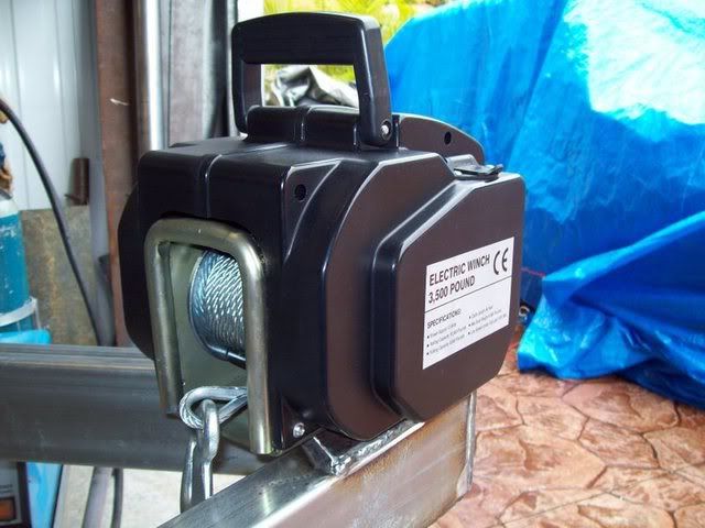
Winch post and cross rail:
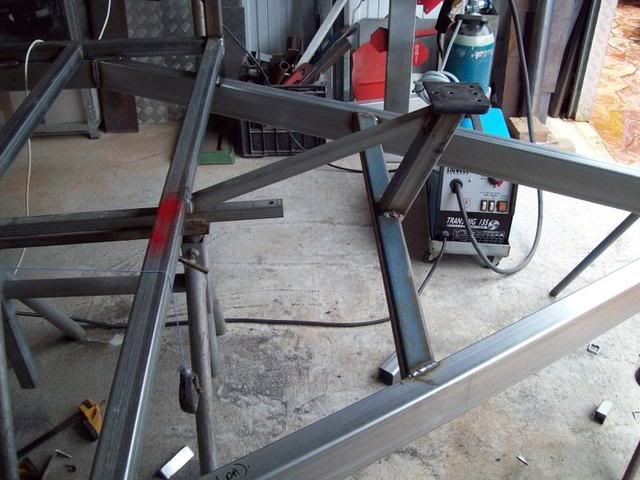
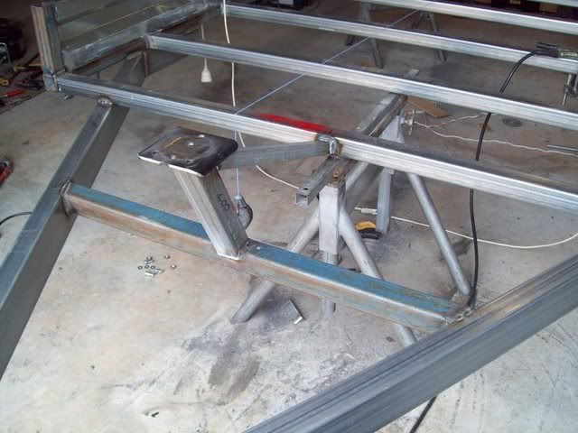
United at last:
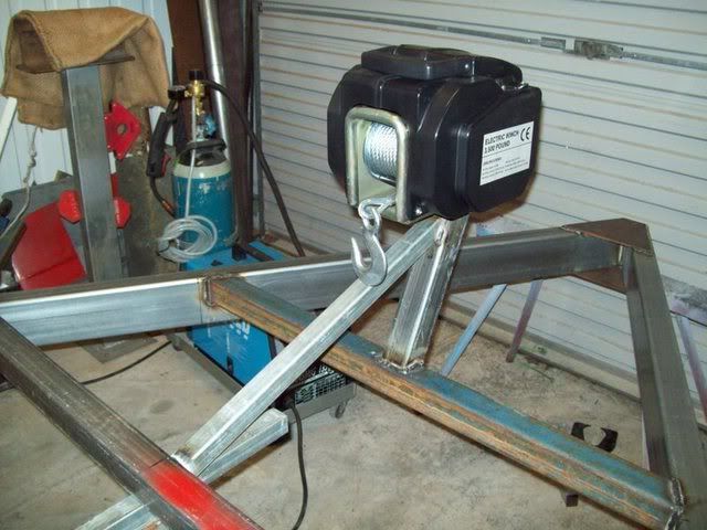 WHEELS
I decided to dress my car trailer up a bit and personalise it. An easy, but potentially expensive, way of doing this is with mag/alloy wheels. Not to be wanting to spend cash unnecessarily, I went to eBay and searched for mag wheels with the following criteria:
o 14 or 15 inch wheels so they would look modern and common tyre sizes (no 17 or 18” wheels here – too dear on tyres!)
o Had to be a set of at least four, if not six (remember the two spares)
o If I couldn’t get six, they must be a fairly ‘common’ design so spares could be chased down (but not too common!)
o Modern styling
o Popular stud pattern – in this case Ford or Commodore (extremely common, and I know I could get the hubs in this pattern as well)
o Width of 6 or 7 inches – good load carrying ability plus cheap replacement tyres
o Already have tyres on them preferably with used, but still legal, tread
o Be within 100km of my house, so I didn’t have to pay freight.
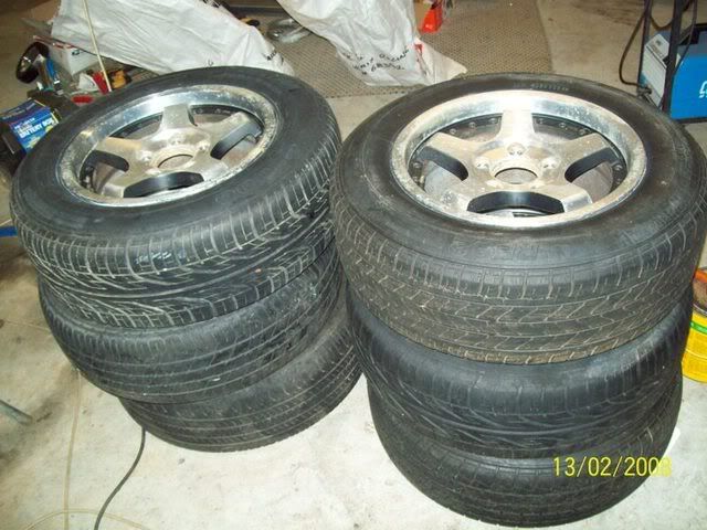
Within a few days of searching, I found some older style but very popular 15 x 7’ Cheviot mags with useable and still legal 206/65R15 tyres off a VS Commodore about 15km’s away, perfect. I waited for the end of the auction, with about 5 secs to spare I pounced (as I did with the winch) and got them for $102 with tyres – bargain of the century! They had had a fair bit of use, but were still in good nick – no dents, cracks or gouges, just a bit of gutter-rash on one. I took them home and cleaned them up. Now to get some spares. I casually asked around at a few local wreckers and scoured the internet (eBay, Trading Post) for Cheviot 5-spoke rims for a couple of weeks, before finally deciding to get serious. Taking a picture of the mags with me, I went back to the same local wreckers and handed out the pictures of my wheels. Within one day Narangba wreckers phoned and said they gave the picture to their delivery driver who goes around to all the other wreckers with parts (Wreckers Hotline here in Brisvegas). Within one day they phoned saying they had located two identical wheels at wreckers at Carindale – perfect! They arrived at Narangba a few days later but the tyres were shot. Narangba obliged by fitting two used 205/65R15 tyres for a nominal fee. $135 later (yes, dearer than my first four wheels but they knew I wanted them, so I paid) and they were mine. Happy now, I had six wheels, all identical, for the trailer and I paid all up $237 for the lot!
Note: Mag wheels do look nicer than steel wheels on the trailer and they are slightly lighter, sure, but they will cost you more. Expect to pay between $15-$30 each for a Commodore steel ‘pursuit’ rim from the wreckers if you want to save some dollars here, or the Ford equivalent if you support the blue oval!
The wheels, look Ok and cheap too:
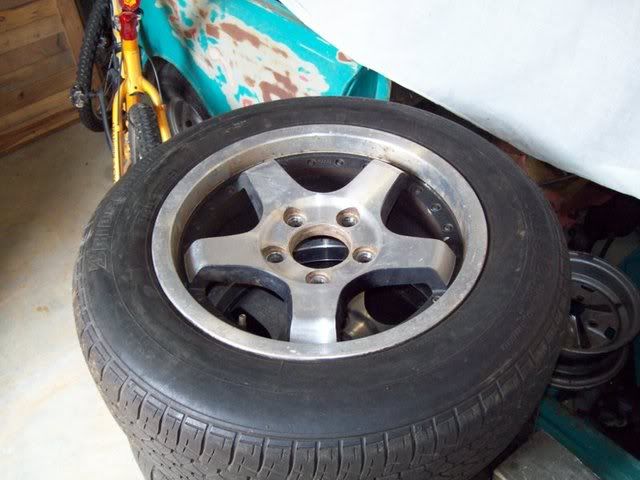
All six:
SPARE WHEEL CARRIERS
While I was waiting for the battery-box to be bent up (more on that later), I decided to tackle the on-board spare wheel carriers. There are two as per the design requirements (see ‘DESIGN’). Because there are two, they had to appear symmetrical in location. I chose in my design to locate them at the front of the trailer, in the location where the tyre rack meets the trailer tray.
Note: By using two spares I gave myself 50% redundancy if I ever had a flat, blow-out etc. I have seen 6’ x 4’ box trailers that don’t come with any spares, they are options! Ludicrous! If you only want to have one spare, centrally locate along the centre-line of the trailer, say on the drawbar. That way weight will be distributed evenly from side-to-side.
Note: the less spares the less cost obviously, but for the sake of an extra $50 or so, I would have the second spare.
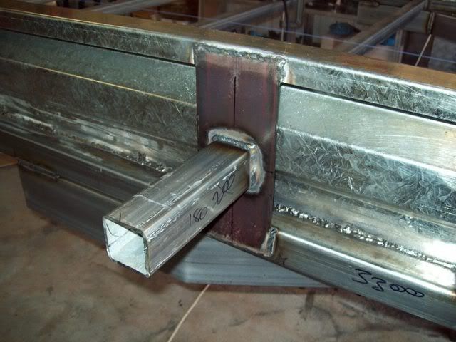
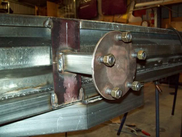
I started the spare wheel carriers by cutting two pieces of 6mm flat bar, 100mm wide by 250mm long (one for each side). Mark out the location where you want the tyre to be located. My 205/65R15 tyres are 600mm in diameter. I didn’t want them to protrude past the front of the trailer (and walk into a dirty tyre all the time!); therefore the mid-line of the spare wheel mounting post would have to be 300mm from the front of the trailer (or, the exact centre of the wheel, which is 300mm). The height of the wheel wasn’t that important, so the wheel mounting post would go in the centre of the plate. Therefore, I made a mark 250mm back from the front of the trailer (remember, the plate is 100mm wide, 50mm this side of the centreline, and 50mm the other side – hence 250mm) and welded the plate to the side panel and to the main rail (make sure the plate is plumb, but if your marking off a plumb corner post like I did, and your marks are equal, it should turn out plumb regardless). I then marked on the plate, a mid-line length-wise and width-wise. This gives me the exact centre of the plate and also reference lines for the wheel post. Next, was to cut the wheel post to the exact length required. Now, this is important – unless you have the exact same offset wheels as mine, your post length will be different. I am using alloy wheels (see above), with a positive offset of 60mm. This meant the wheel had a quite deep reverse dish. Now, where I decided to mount the wheels was where tyre rack was to be mounted (more on that later) so I had to allow for the 30mm RHS that would be welded to the outside of the trailer tray. This combined with the 150mm depth (wheel mounting face to outside of tyre) of the wheel, dictated the post length was to be 180mm. By using a 5mm plate on the end of the post for the wheel to bolt to, gave me a 5mm clearance of tyre to trailer side distance. Perfect! So, now that I had my post length, it was time to cut it (again, I cut two, one for each side). I then marked centre lines up the sides of each face of the post, to align with the ones on the post mounting plate, so the post would be dead-centred when I welded it. I tacked it on, made sure it was level and plumb, and then fully welded along all four faces.
Spare wheel bracket and post:
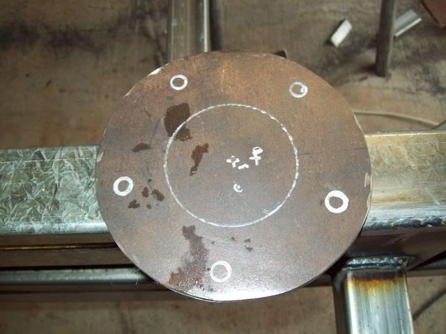
Next came the wheel mounting plate. I used the wheel centre boss as an indicator of how big the diameter of the plate was to be (obviously, it is a circular plate). The mounting boss for the wheel was 150mm – great, I had some 5mm flat bar 150mm wide in the rack. I scribed a 150mm diameter circle on the plate and proceeded to cut it out with an angle grinder. Once the shape was roughed-in, I cleaned it up with the linisher until I had a good round circle. I placed the circle on the wheel mounting face and marked out the stud holes.
Wheel mounting plate ready to be drilled:
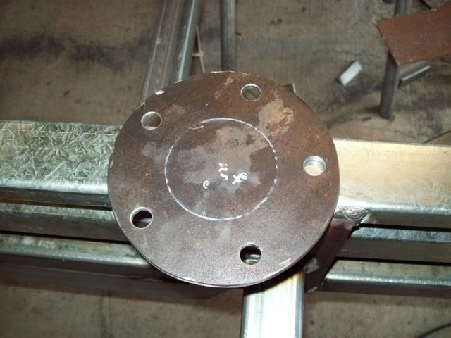
Once they were centre-punched, I drilled them out. Now, I had some 9/16th wheel studs left over from a previous job, enough to do both spares. But you can obtain them from any reputable fastener place. Also, Commodore and Ford use ½-inch studs, but I just used what I had spare.
Note: If you don’t want to use proper wheel studs, just use some ½-inch bolts that are the right length and weld the heads to the back-side of the wheel mounting plate.
Note: Generic ½-inch bolts will be cheaper than the fluted wheel studs. The bolts do not have to be high tensile either.
Plate drilled:
The fluted wheel studs:
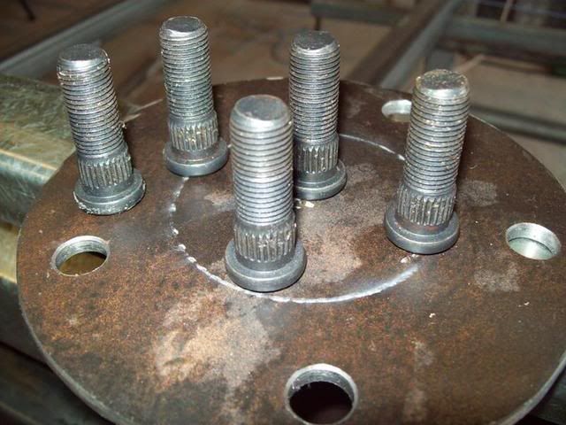
De-burr the holes and drive the fluted wheel studs home from the rear-side in. You will need a big hammer for this and a sturdy bench. They take some pounding! Try not to bend the plate. I did mine on the bench vice, with the jaws just wide enough for the bolt.
All together now:
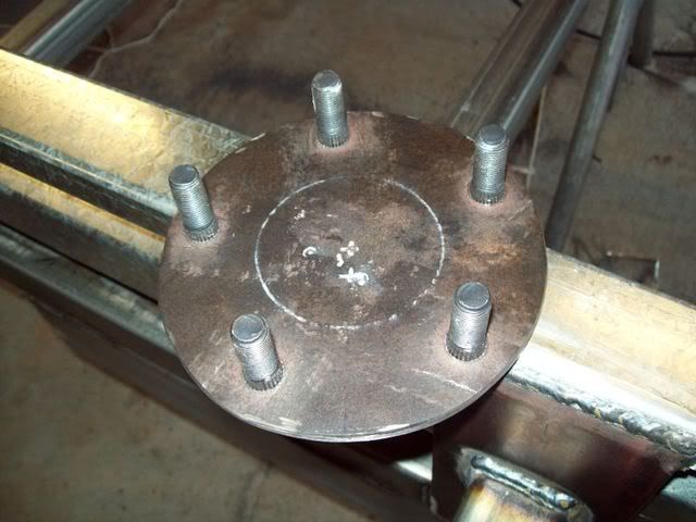
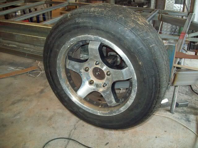
Test fit - perfect!!:
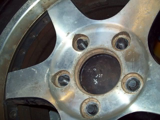
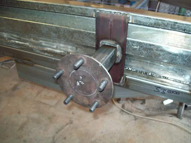
Locate the centre of the wheel mounting plate, and draw two lines across the face at 90 degrees (right-angles). Align this marks with the existing marks on the sides of the wheel mounting post and tack weld. Test fit the wheel to the carrier to make sure you have the right clearances and alignment (no use repeating your mistakes on the other side or after you have fully welded it). Ensure the plate is centred, plumb and square and then fully weld. Finished, one spare wheel carrier! Now, go do the other side with same dimensions.
Wheel mounting plate welded in place:
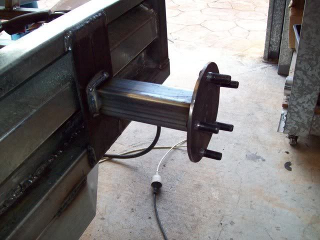
Test fit of the wheel - great!!
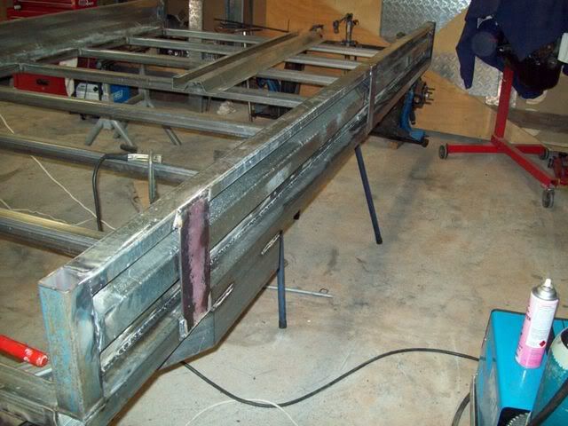
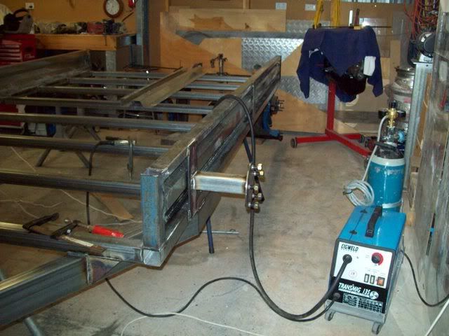
Side 2:
 TYRE RACK
The wheel rack is a great feature if one day, you intend to do a little bit of motorsport with your Mini (or someone else’s). For a bit of extra cost and time, you can have the capability of carrying your spare race tyres, or road tyres, to the meet and look uber-professional. The dimensions for the tyre rack that I chose was specifically for the Mini or other small car like a Gen. 4 or 5 Civic, Mirage etc. To be specific:
o The distance from the underside of the rack to the tray floor is not huge, you wont get a Landcruiser to poke its nose under there
o The tyre areas are not overly tall – my 15” trailer tyres wont fit, but my 14” Enkei’s with the low profile 205/45R14 Dunlop’s will
o The locker part in the middle section caters specifically to house the winch and hand-controller out of the weather
o The angle with which the rack converges to the centre will not allow wide cars to fit underneath – Commodores will struggle
If you have a look at the dimensions on the drawings, you will see what I mean. Right, let’s get into it. The first part in the tyre rack is to do the front frame ‘hoop’. It consists of three pieces – two side pieces and one top piece. All the parts of the frame are 30mm x 30mm x 2mm Duragal RHS. The front hoop is joined onto the trailer at two points, at the front corner posts where the structural integrity is greatest. It bends at 10 degrees in the middle where the rack proper is, then joins the top piece. Start by marking the dimension where the 10 degree cuts will be (see dimensioned drawing), and take a slight wedge cut here to allow for the RHS to bend inwards. Do this to both side pieces at both points.
Note: The dimensions for the rack are customised to my needs. You can make it shorter, taller, wider etc to cater for your own. Remember, the taller it is the more wind it will catch, the shorter, the lower the car to fit under etc.
Tack weld the top piece to the side pieces, then clamp the side pieces to the trailer sides. Take heaps of measurements here to make sure its all square and level. Once everything is fine, weld the top piece on, and weld up the cuts where the 10 degree bends are. Tack weld the front hoop the trailer corner posts.
Front hoop tacked on, no mid-brace:
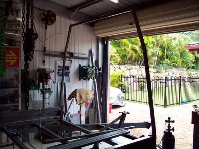
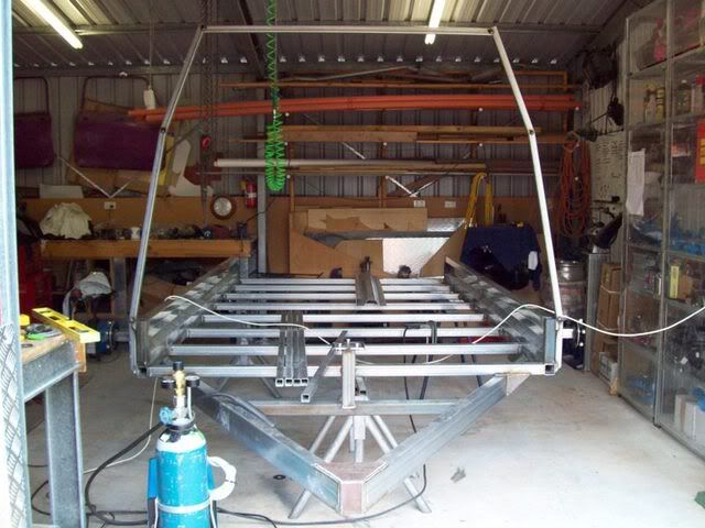
Now, weld in the mid-brace rail at the point where the upper 10 degree bend is. This is one of the rails the tyres will sit on. Now, tack on the longitudinal pieces that will support the locker sides and the end sides for the rack. Make sure they are all level and square to the front hoop. See pic for the pieces that I mean. They should be all 350mm long.
Mid-brace tacked on:
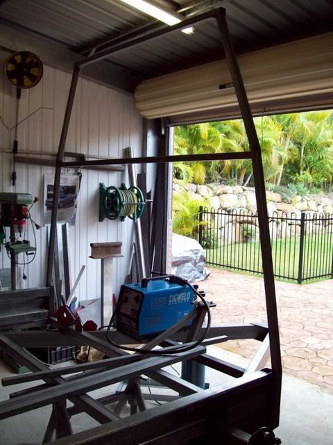
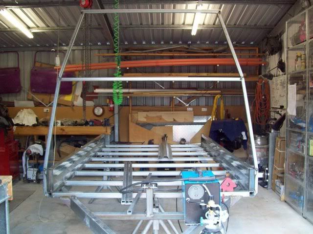
Upper longitudinal pieces that make up the locker part:
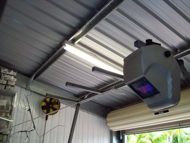
Next, tack on the lower longitudinal pieces – the locker side ones should be plumb with the upper ones, and the outer ones will be wider as the rack gets wider at the mid-brace point. Once again, make sure they are all level, plumb and square before tacking. Now that you have all the longitudinal pieces in place, its time to add the lateral (cross-wise) pieces, or the rear hoop – which again is in three pieces – the top, and the two sides. Tack the rearmost top rail across the upper longitudinal pieces, and then tack the rearmost mid-brace across the lower longitudinal pieces. Now, comes the hard part – the two side pieces of the rear hoop bend in two planes, i.e. they bend in towards the centre of the trailer and they bend more vertically. The good thing is that this happens at the came point. Locate the dimensions where this bends takes place (an initial 10 degree bend where it comes off the tray, and another 10 degree bend where is converges halfway up), and make a cut with the angle grinder a cross four inside faces (upper bend only, do the lower one on the inside face only), leaving the outside rearmost corner intact. Mark this outside face so you know which one it is. Manipulate the outside side piece so that it connects with the mid brace, the top rail and the trailer sides. Tack it in place. Do the same with the other side. Now, you should have the rack frame all completed.
Rear hoop tacked into place:
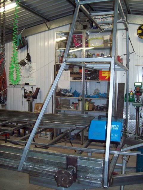
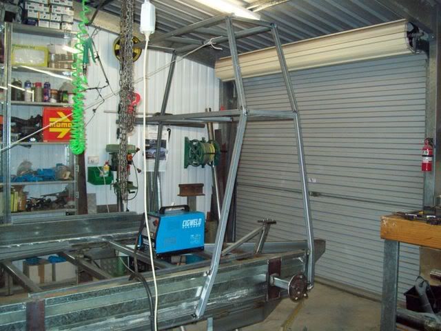
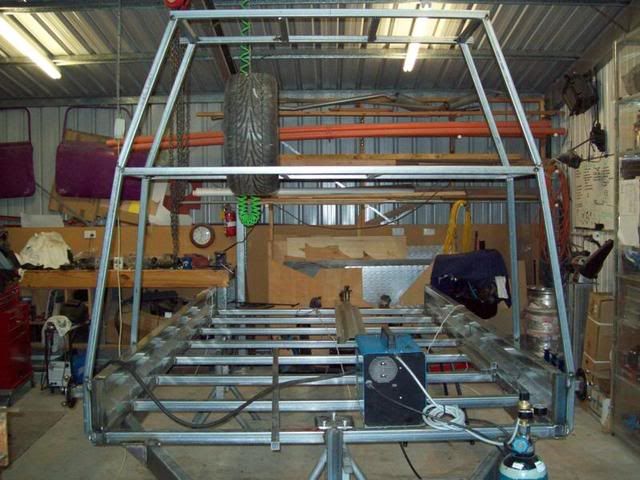
Test fit of wheels:
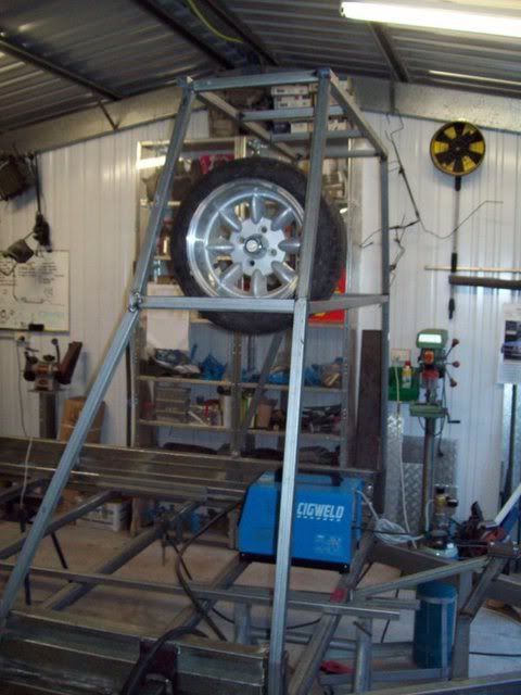
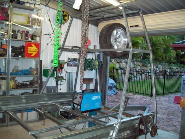
Take some measurements so that the bends and distances are the same on both sides, and then fully weld it at every junction, or cut, except where it attaches to the trailer, this is only tacked on. Now, cut the tack welds that hold the rack to the tray, and remove the rack. Now that it is fully welded, it will retain the right shape, and its easier to work on it at ground level, than up on top on the trailer. Weld up the lower 10 degree bends now that you can get to them off the trailer. Now, weld in the vertical pieces that form, the front and back of the locker. These pieces align themselves with the longitudinal locker pieces already in place. You now should have six sides to your locker part. Test fit the tyres in their locations to make sure you have enough room – I had heaps! Next step is to slash-cut the very ends of the front and rear hoops, to make that nice streamlined look. I then decided to put in some mid rails inside the locker – these would act simply as shelve supports for an upper timber shelf.
Note: Upper shelf purely optional, I needed to store a bit of stuff so an upper shelf was ideal.
Rack off the trailer for finishing:
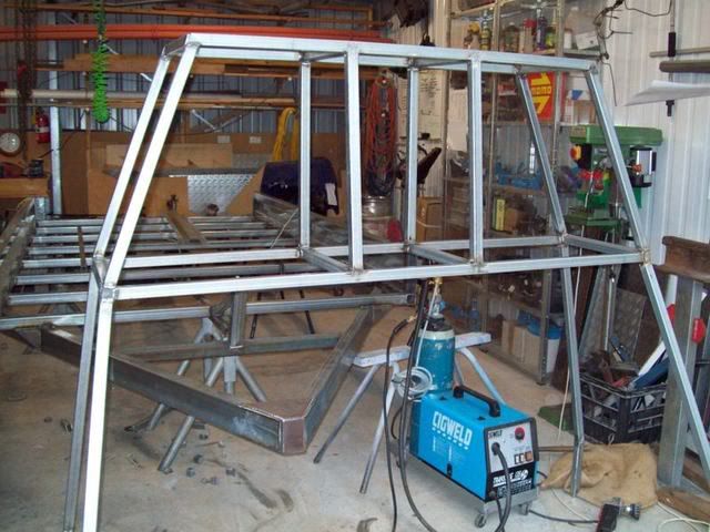
More test fitting to see that it all looks OK:
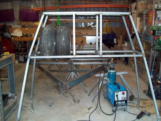
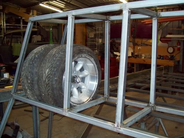
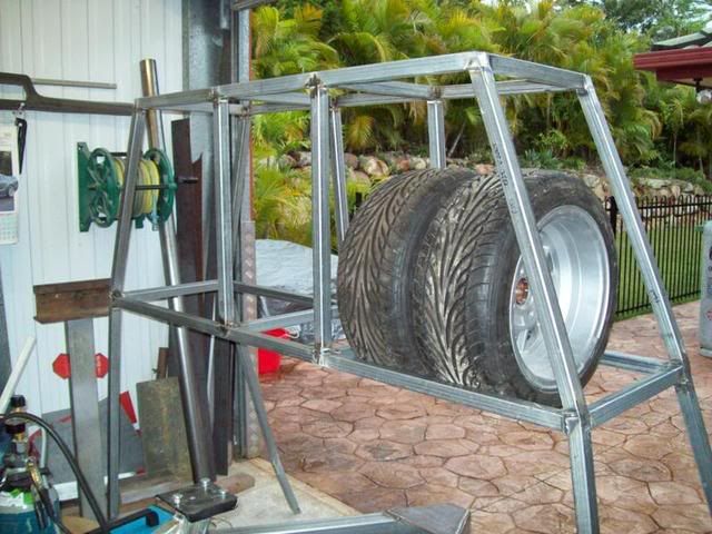
Shelf rails:
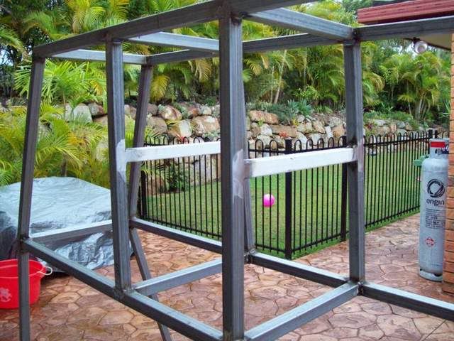
Now, grab the flap disc and grind off all the protruding welds where the locker panels and side panels will be affixed. If your welds have good penetration, this will not affect the integrity of the frame. Next job is to construct a weather-proofing door jamb for the locker door. Simply take some 1.6mm gal sheet and cut four strips – two the height of the locker and two the width. They will need to overlap the opening by about 10-15mm so they can be clamped while being welded. Mitre the corners and tack together. You should end up with a rectangle slightly longer and wider than the locker door aperture. Now, cut-out the corners where the rails intersect so it will fit flush against the inside face of the aperture opening – tack it in place ensuring the overlap is even all the way around. Now, once you are happy with the fit, completely weld the jamb into place along the front face. You now have a weatherproof lip to seal the door against.
Locker door jamb in progress:
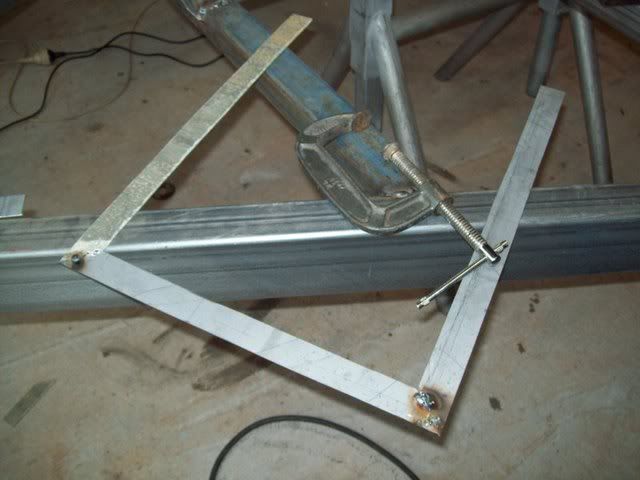
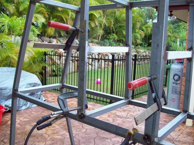
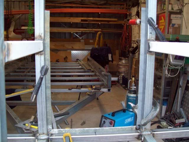
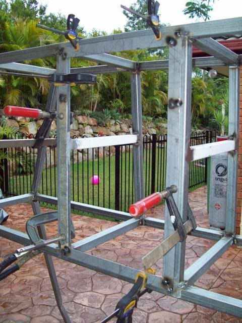
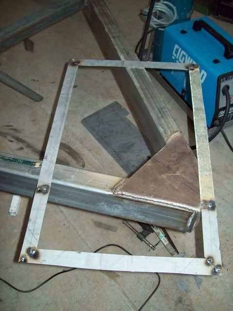
Complete jamb:
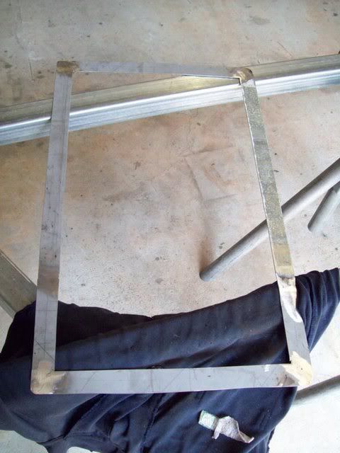
Complete jamb with cutouts for the corners:
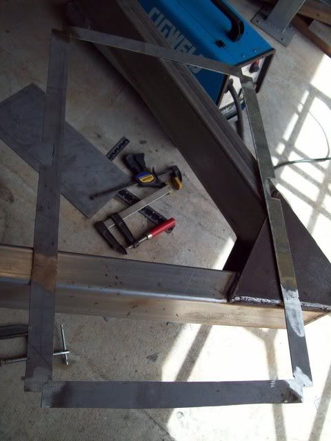
Fully welded in place:
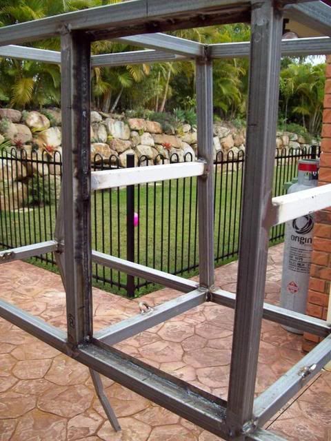
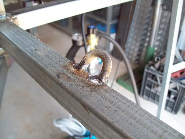
The next job is to weld in some tie-down points on the rack whereby a chain passed through your spare tyres can be locked off for security and safety reasons. Hint: Go to Bunning’s, and in the chain section they will have a waste basket where they place all the chain off cuts. These half chain loops are ideal as mounting or tie-down points. I chose the biggest loops I could find, four of them, and welded them on to the lower longitudinal pieces on the rack – see picture for detail.
Tie downs:
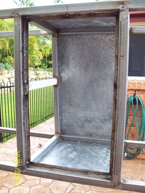
The next job for the rack was to enclose the locker with the five sides and one door. Cut the 1.2mm gal sheet that you ordered (see cut-sheet) to size. This is a pretty simple task and just involves transferring the measurements from the frame to the sheet and cutting it out. I bought a pair of air shears from Trade Tools for $49 specifically to do this job, and they work a treat. However, I know I will have lots of work for the air shears in the future. Do yourself a favour, by a pair. Once all the sides were cut and filed, I then proceeded to mark out equal spacings for the pop-rivets that I would be using. I decided on 60mm spacings – yours can be different. Grab some silicone here and lay a bead of it along the mounting faces of the frame of each panel. This will ensure water-tightness of the locker. Rivet on the sides, top and bottom panels, ensuring they are square with the frame with blind, sealed rivets. These ones are the only ones that are water-tight.
Back, top and bottom done:
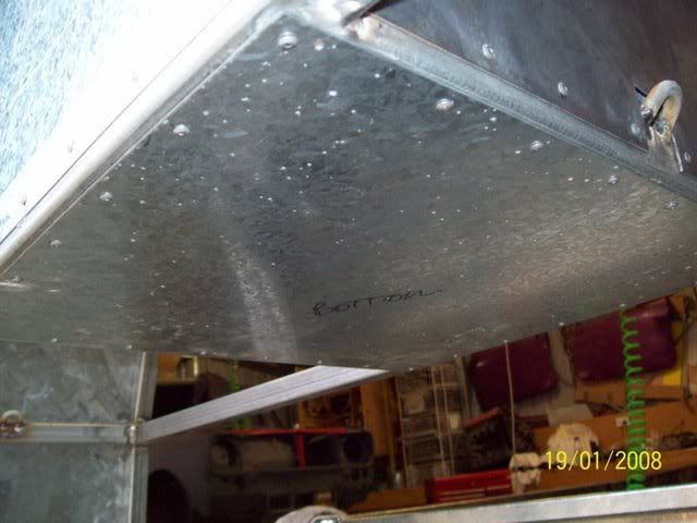
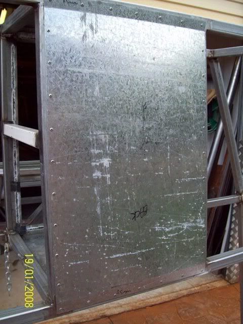
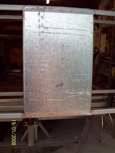
Sides (notice cut-out for tie-down loop):
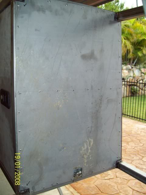
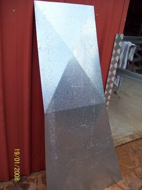
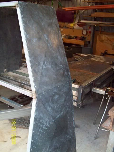
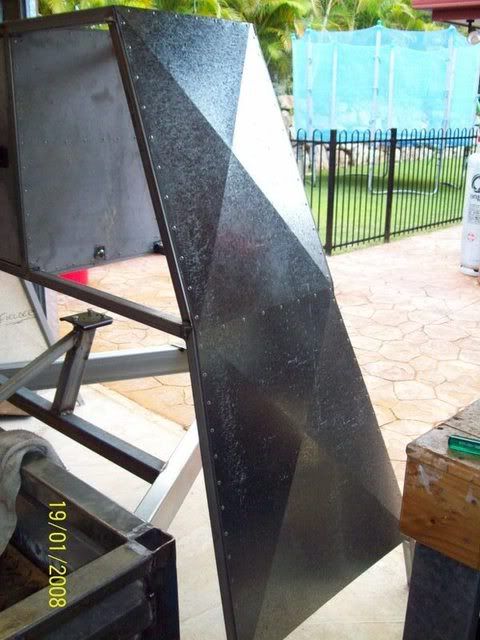
Now its time to tackle the large side panels, which will be done in one piece. Once I had cut my side pieces out, and checked that they fitted perfectly, I took them to the local sheet metal workshop and had them press some creases in the sheet using the pan brake. This will give the sheet a lot of added stiffness and stop the panel drumming with the wind or vibration. I creased diagonally top and bottom of the mid brace – see the pics for details. Now that you have the side panels complete, rivet them on as per the locker but with normal blind rivets. Sit back, drink beer, and enjoy fruits of your labour.
Sides prior to riveting, notice creases to add strength:
Riveted in place:
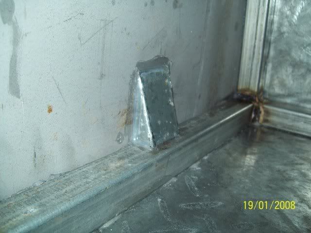
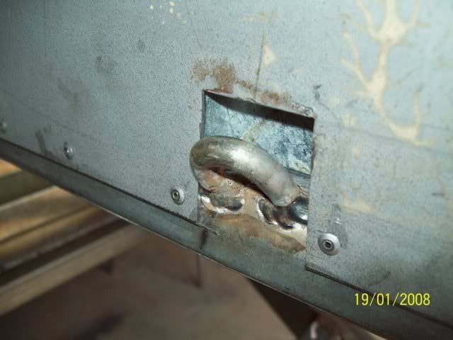
Now, where you placed the chain link tie-down points needs to be enclosed. It’s easier from the inside. I simply bent up in the vice a pair of tapered covers to go over the cut-out in the panel where the tie-down points are. Simply, I just siliconed them in place.
Cover piece to seal around the chain link:
From the outside:
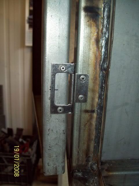
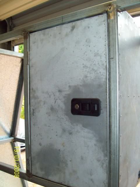
The last item to be done with the rack, other than painting, is the locker door. In the plans are detailed drawings of the locker door, to take to any sheet metal workshop to bend up if you don’t have your own pan brake. There is a gap of about 3mm all the way around for my door. I started by test fitting the door to the aperture and ensuring it was flush with the outside face when fully closed (actually, there was a bit of a setback to the door and it wasn’t quite flush, but once the foam seal was put in to seal around the door, it would sit pretty much flush with the outside face. The dimensions of the door have catered for this. Now it was time to mount the hinges. I used a pair of stainless steel hinges from Bunning’s, and I mounted them to the door using the same blind pop rivets I used to mount the locker sides with. Locate the door in the aperture and mark the hinge position top and bottom of each hinge, open the door, locate the hinges with the marks you just made, and mark out the rivet holes. Once you have drilled the rivet holes and riveted the hinges to the frame, it should swing sweetly and not bind anywhere.
Hinges riveted:
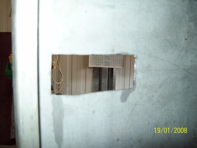
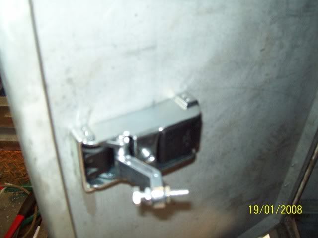
The last job is to cut-out for the latch mechanism. I bought a flush mount lockable latch from United Engineering Supplies, in black, for $14. Locate the latch, cut out the aperture and test fit. You may have to adjust the depth of the threaded bolt that catches the back of the frame, but that should be about it. Seal the corners of all the sheets from the inside with silicone to make them watertight and you’re done. Your rack is now complete.
Hole for latch:
Latch installed:
Door complete:
 RAMPS AND PIVOT POINTS
I was lucky in that I had a set of ramps from another trailer at my disposal. The were made out of 40mm x 40mm x 2.5mm RHS stiles and 25mm OD pipe rungs. I space the pipe at 200mm centres and the overall length of the ramps were 2000mm – which I subsequently cut down to 1670mm to suit the new trailer. I slash cut the ends of the ramps parallel with the ground and welded ‘feet’ on them from 5mm flat bar. I then welded the pivot points on.
Pivot lugs:
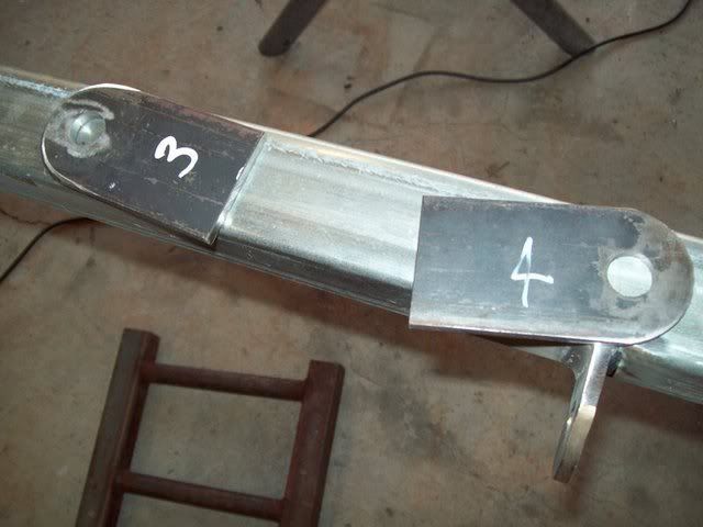
Lugs welded on:
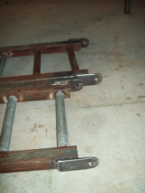
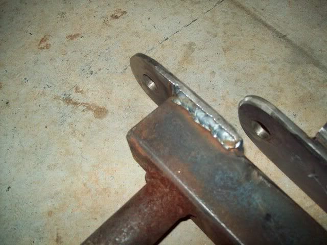
Feet welded on:
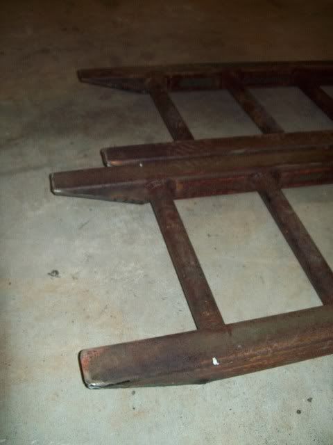
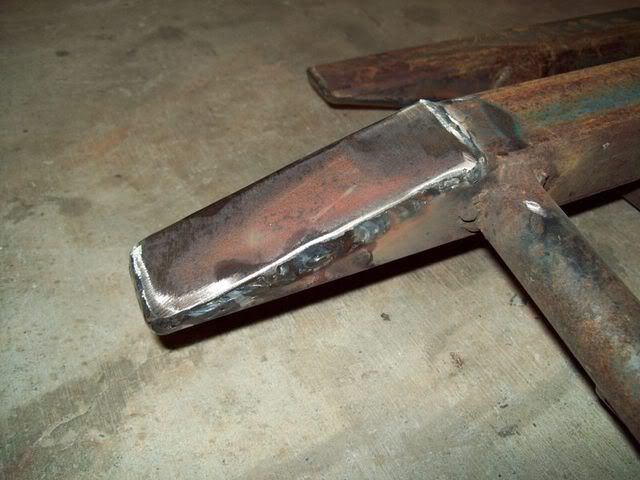
Now my original idea of a quick release hinge or pivot point came to fruition in the form of mounting lugs and 16mm round bar pins that would be held in place by R-clips. This seemed like the easiest way to do it. I located some 16mm round bar from the local steel merchant for $10 and welded 32mm hole-saw plugs made from 5mm flat bar onto the ends – they looked like giant knitting needles which was exactly what I was after. I ground down the R-clip end to a conical shape and drilled a hole through the round bar to take the R-clip. Naturally I countersunk these holes on both sides to make it easier to located the R-clip in the hole. The ramp lugs were made from 6mm x 50mm flat bar, cut to 100mm long. The 16mm pivot hole was drilled 25mm from one end, and that same end rounded to forma 25mm radius curve. All four of these were the welded to the outside of the ramp stiles. See the pics for details. The lugs were left with a 50mm proud length past the end of the stile. The trailer lugs were identical to the ramp lugs, except they were 50mm in length. These were welded onto the back face of the last cross rail. Make sure that the distances you are mounting them in from each side are identical, and that each lug is square and plumb. Weld the lugs to the frame. Note: I had to back-grind my ramp lugs on the outer faces at an angle of 45 degrees on the outer face to allow for the depth of the weld on the trailer lug inner face. Other wise, they would bind through their total arc-movement. This picture best describes it. Another way to escape this minor problem, is to move the pivot hole closer to the curved edge of the lug.
Pivot lugs on trailer:
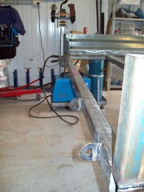
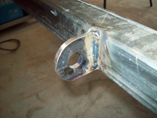
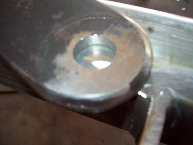
Tailgate ones back-ground to allow for smooth swing:
Pivot points welded to tailgate and pivot pins located:
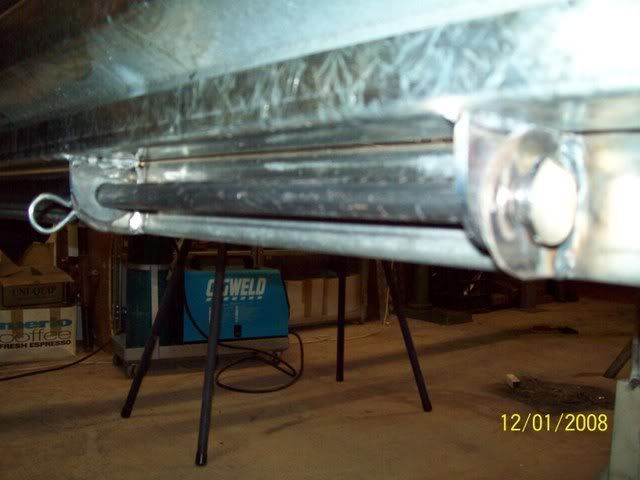
R-clip to hold in place:
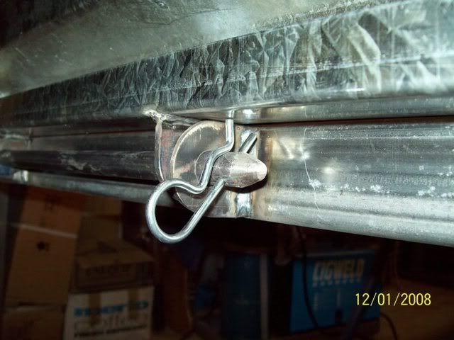
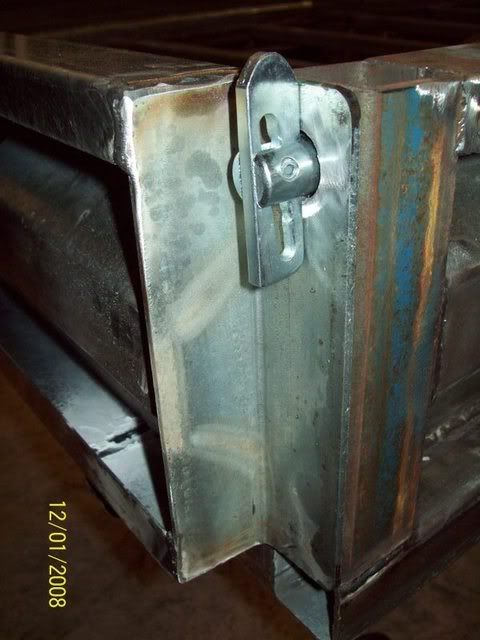
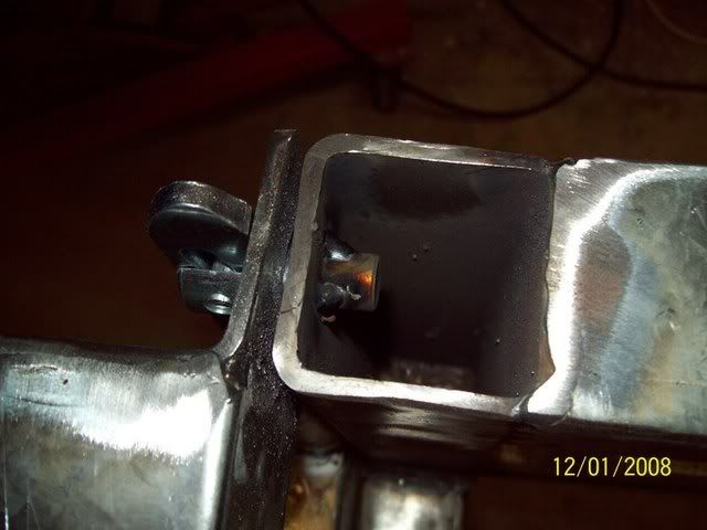
While I was there, I mounted the anti-rattle catches:
 SUSPENSION MOUNTING POINTS
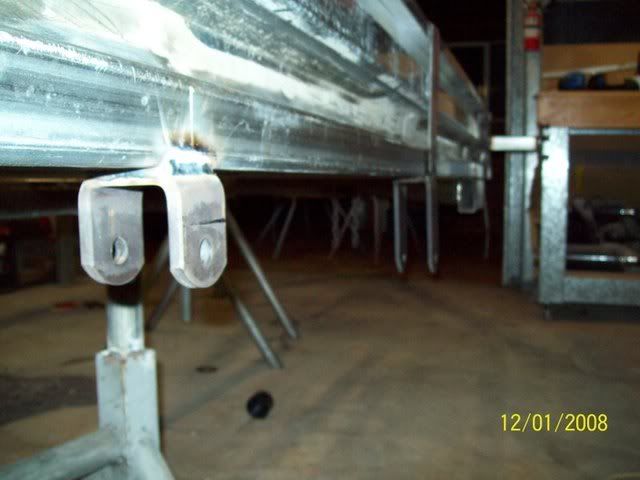
If you bought a pre-made, matched suspension from a trailer supplier, it should come with all the mounts ready for welding onto your frame. The mounts consist of front perches for the springs, rear perches for the hangers and mid bracket for the rocker assembly (tandem trailer only).
Note: You can opt for a single axle-trailer, but a tandem offers some added benefits like added stability, greater load carrying, control and stability in the event of a flat or blow-out and less pitching than a single
Note: Considerable savings are to be had choosing a single over a tandem. However, you must decide early the load carrying capacity you need, as DOTARS legislation does not allow single-axle trailers over 2.0 tonnes GTM
Begin by marking out the mid-length distance of the trailer along both main rails. This is the geometric centre, front-to-back, of the tray. This point we will use as a datum. Mark forwards towards the front of the trailer the manufacturer specified hanger distance for the front hanger, and then from the mid-point mark backwards towards the rear the rear-most hanger point. Do the same on both sides. Double check the measurement that they are the right measurements, and that they are the same on both sides. Now, turn the welder up, and tack on the front perch making sure it is aligned with the chassis rail. Do the same with the centre bracket that holds the rocker assembly, and the rear perch. Now eye them to ensure they are all aligned and plumb. If you are happy with this, weld them to the chassis with nice strong and penetrating fillet welds. Do the other side. Your suspension hangers are now done!
Suspension points welded in place:
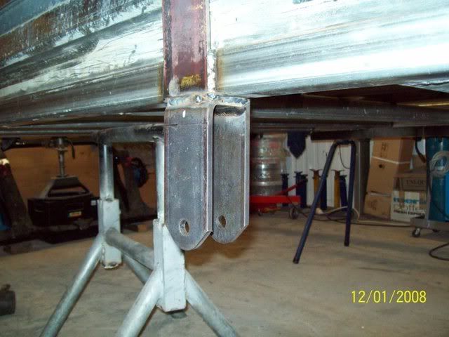 COUPLING
The coupling I purchased for the trailer has a rating of 3500kg’s, and has an integral handbrake lever. It is a long unit. The length of the handbrake dictated two pieces of 6mm steel for plating the drawbar, so the coupling could be mounted to it. Now it is time to drill the holes for the coupling. 12mm HT bolts are used for this so the hole I drilled was 12.5mm for a bit of clearance. Mark the holes by placing the coupling in position – make sure it is on the centre-line of the trailer. Centre-punch the holes, and drill with a pilot, I used 7mm, then drill again with the 12.5mm. De-burr the holes with your countersinking bit, and test fit the coupling. If all is good, move onto the next job.
Note: Handbrake is an option here, as is hydraulic brakes and override coupling. Even Treg, Trigg or other couplings can be used
Note: You can go the hydraulic override brake route here, the coupling is considerably dearer due to the integral master cylinder and hydraulic lines
Test fitting the coupling and marking of holes:
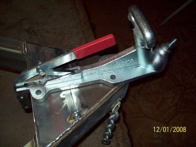
Holes drilled:
Welded chains on while I was there:
HIGH MOUNT STOPLIGHTS AND WORKLAMPS
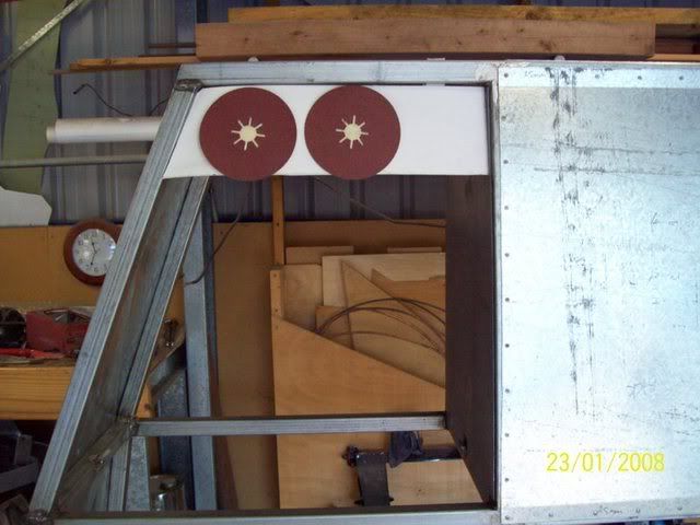
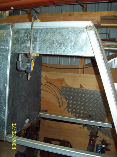
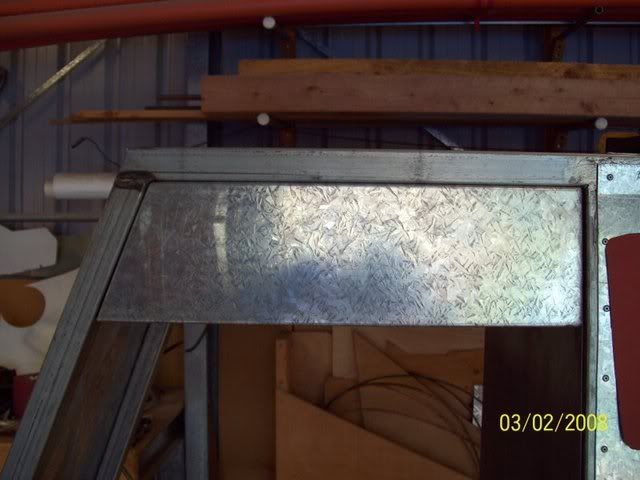
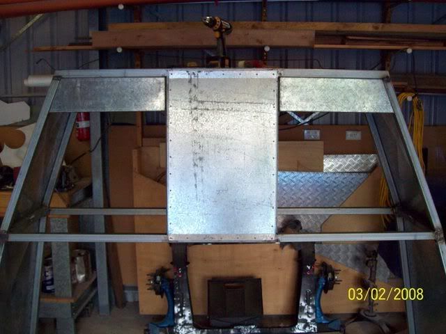
The next job took me back to the tyre rack. After having a look at a lot of tilt-trays going around, and understanding how low my taillights were going to be on the rear of the trailer, I like more and more the idea of high-mount taillights. I had a serious look at the space available to me, and where I could put some extra lights – indicator/stop/tail cluster, LED of course. And it came to me that I had some extra space at the rear of the rack, up high, due to the fact that the tyres would always be loaded from the front (who wants to swing heavy tyres up onto a rack while leaning over the bonnet of their car?). So, it came to me that if I made up a small in-fill panel at the rear, I would have enough room to mount the lights, and also, just maybe, have some spare room available to mount a set of worklamps. I believe it can be very aggravating loading or unloading a car in the afternoon, only for it to take longer than expected and get frustrated because you cant see what you are doing as darkness is falling. It’s the same with those longer than expected race meetings on a Sunday afternoon, or traffic problems on the way home from a meet. So, a set of worklamps with a flood beam would make sense and make loading or unloading in darkness a hell of a lot safer. The maximum depth I could come down from the underside of the top rail for the rear hoop was about 120mm. This would allow me to still have the 14” tyres on board, as the curve of the tyre would still miss the in-fill panel. The panel would take follow the shape of the rear hoop and locker frame, so the shape was dictated by the position. I cut out the 1.2mm gal-sheet to size (see drawing) and had the sheet metal shop bend it to shape. The fit well. And then I pop-riveted them to the underside of the top rail, and the inside of the locker frame and rear hoop – see pictures for detail.
Template of infill panel to guage depth needed for lights:
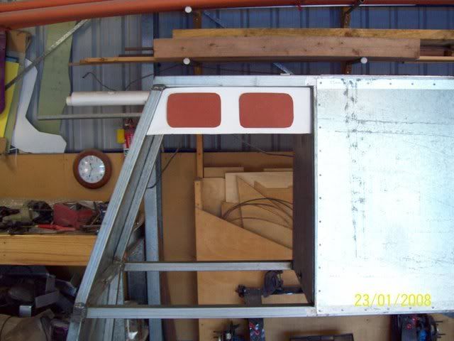
Other lights too:
Infill panel clamped in place:
And riveted:
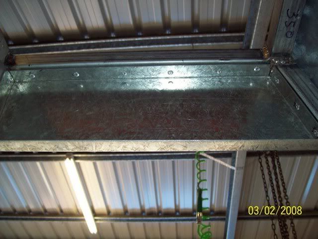
Both sides:
Next came the agonising decision of which lights to choose, what format should they take and what size should they be. I like the adage with taillights that bigger is better, but when you have a limited amount of space, you cant always subscribe to this point-of-view. I went through the exercise of jumping on the web and downloading specs from many LED taillight manufacturers – Hella, Narva, BrightLights etc Then, I cut-out many cardboard outlines of all the different LED shapes and test fitted them on the panel, and on the rear of the trailer. The following points came out of the exercise:’
o The taillights should be bought as a cluster unit, as individual stop/tail/indicator lights take up more space and cost more
o The indicator should go to the outside
o The high-mount lights and the low-mount lights should be the same manufacturer and model number for ease of maintenance and integrity of ‘look’
o The number of LED’s does not necessarily mean a brighter light
o They will need to be ADR approved (a lot on the market, especially eBay, weren’t)
o They needed to be big enough to be seen easily, but small enough to fit into the space required
o The high-mount lights needed to be small enough to have the worklamps mounted beside them.
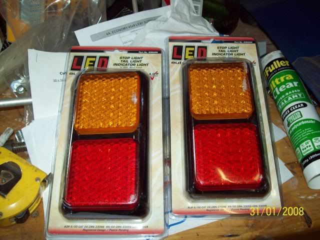
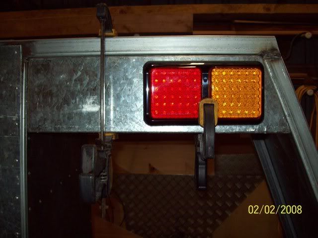
To this end, here are some pics of the mock-ups and the lights I was looking at. Eventually, I decided on LED cluster units from ‘LED Autolamps P/L’ from there ‘80 Series’ range. The model chosen were the 80BAR clusters, 80WM reversing lamps, the 35ARM clearance lights and 35BLM number plate lamp from their ’35 Series’. There are a couple of hundred bucks worth of lamps in here, but they came out much cheaper then the Narva or Hella alternatives.
Note: Use the lamps you are happy with, even old ones lying around. I went for no-maintenance and long-life units
Note: By substituting normal filament-lamp lights for LED’s there is some saving to be made, about 50%. However, my view was that it only takes one ticket for a blown indicator/stop/tail light to make up the difference. With a 8000 hour life expectancy for LED’s, they should keep on working long into the future (like 10-15 years, ever wonder why trucks and buses use them now – less maintenance!). Further, the whole LED light assembly is sealed in an epoxy block which makes them shockproof, rustproof, impact proof, vibration proof and waterproof – something which filament lamp based taillights aren’t.
The lights were purchased from Coventry Auto parts, the local distributor and test fitted. They were a really well made unit. They also gave me space for some worklamps as I had hoped. Again I went through the Hella and Narva on-line catalogue looking for some worklamps of the right size and shape and output. I settle on the Narva 72480 recessed dual-beam flood lamp. It fit the space nicely, and drawback is that is fixed in terms of direction. Unperturbed, I believed it had such a large beam spread that two lights high-up should cover the whole trailer and then some. Again back to Coventry. Instead of coming away with the Narva items as I’d hoped, I bought some Britax ones that were half the price and moveable. Thanks to the Coventry sales person, I save bucks and most likely got a better item. I then proceeded to mark out the mounting holes for the high-mount and low-mount lights. I decided to use 6mm nutserts everywhere instead of nut and bolt, it just made life easier. Also, if they were inserted now, they would get some rust-protection once it was all painted. Another thing I did was to drill the cable holes where the leads would come through. Because all the lights had single insulated wires, I decided to use rubber grommets to protect them against chafing from the metal panels. Small rubber grommets can be bought from Clark Rubber from about $0.99 each. Better insurance and cheaper than blowing a fuse and having no lights due to a short. That’s it, the light’s were done!
80-series lamps from LED Autolamps:
80-series Led lamps test fitted:
Nutserts in place:
[img]http://i18.photobucket.com/albums/b117/archangel007/Album%206%20-%20Trailer%20Build


