Ausmini
It is currently Mon Jul 21, 2025 9:10 pm

All times are UTC + 10 hours


Post new topic Reply to topic  [ 5 posts ] 
Author Message
 Post subject: Alternator wiring
PostPosted: Sun Apr 02, 2017 7:10 pm 
Offline
1275cc
1275cc
User avatar

Joined: Wed Mar 30, 2005 8:54 pm
Posts: 2010
Location: Greenhill, SA
So, my deluxe project is well under way. Next step will be brake lines, and wiring.

The car was originally fitted with a generator, wired positive earth. Half the loom was melted into one another with the trusty non-fused park light circuit being the culprit. It's now going to be a new front loom, from scratch, with proper fuses, relays, and deutsch connectors throughout.

I've got a nice shiny new 70A alternator, but now i need to plug it in.
Image

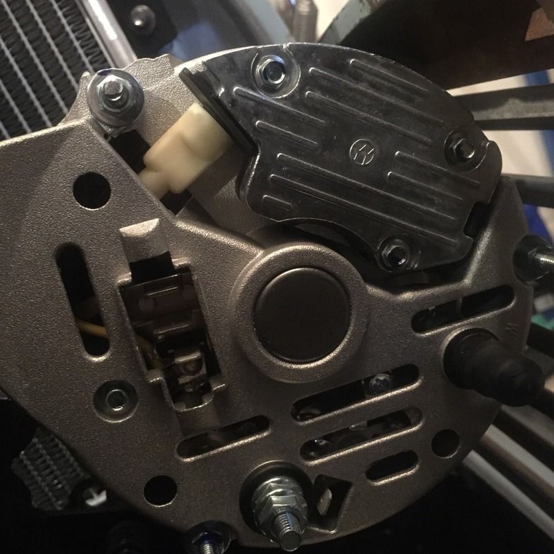
The stud at the bottom is marked B+ which is easy enough to figure out, but I'm looking for any information/diagrams on what to do with the three male spade terminals on the left, and maybe even the single spade terminal at the bottom, next to the B+ stud.

Any and all advice welcome!


Cheers,

_________________
Cheap, Fast, Reliable. Choose two.


Top
 Profile  
 
 Post subject: Re: Alternator wiring
PostPosted: Mon Apr 03, 2017 10:38 pm 
Offline
998cc
998cc
User avatar

Joined: Sat Dec 03, 2005 2:23 pm
Posts: 955
Location: Canberra, ACT
These always drive me batty.

The three seems to "euro connector". 2 Large B+, small IND

The small spade near the nut listed as AUX - implies always powered. (?)

http://jasoceania.co.nz/articles/lucas-alternators-dual-terminals

<edit - better info>


Top
 Profile  
 
 Post subject: Re: Alternator wiring
PostPosted: Tue Apr 04, 2017 9:25 am 
Offline
1275cc
1275cc
User avatar

Joined: Wed Mar 30, 2005 8:54 pm
Posts: 2010
Location: Greenhill, SA
Magic, thanks!

_________________
Cheap, Fast, Reliable. Choose two.


Top
 Profile  
 
 Post subject: Re: Alternator wiring
PostPosted: Wed Apr 05, 2017 7:22 pm 
Offline
1275cc
1275cc

Joined: Thu Dec 09, 2004 6:57 am
Posts: 3022
Location: JIMBOOMBA QLD.
These Alternators are Heavy Duty. They produce 70 Amps on Demand. Make sure that you add an extra 6 mm Cable from the B+ Stud to the battery + solenoid terminal. This helps get the output Amps to the battery. If you use standard size wires you will be wasting your time fitting this Alternator to your Mini. The two large spades and the B+ Stud are a common connection, Same output. Small Spade is is D+ meaning warning light terminal. The Small spade next to the B+ Stud is also B+ used for connecting a suppression condenser, if Alternator does not make any whistling sounds through you sound system speakers leave it unused. The W terminal is only an AC Phase output used when using this Alternator on a diesel Machine with electric Tacho, Do not use it on a Mini.

_________________
DID I MENTION THAT I AM THE BEST SUPPLIER FOR MINI ELECTRICAL PARTS AND REPAIRS?
"Let us remove your "SHORTS"


Top
 Profile  
 
 Post subject: Re: Alternator wiring
PostPosted: Wed Apr 05, 2017 7:51 pm 
Offline
1275cc
1275cc
User avatar

Joined: Wed Mar 30, 2005 8:54 pm
Posts: 2010
Location: Greenhill, SA
Excellent advice, thank you. I'm wiring the car from scratch, and will be using wire that is up to the job. Electric Power Steering is in the future, hence the 70A unit. Relays and fuses-a-plenty!

_________________
Cheap, Fast, Reliable. Choose two.


Top
 Profile  
 
Display posts from previous:  Sort by  
Post new topic Reply to topic  [ 5 posts ] 

All times are UTC + 10 hours


Who is online

Users browsing this forum: fuzzy-hair-man and 68 guests


You cannot post new topics in this forum
You cannot reply to topics in this forum
You cannot edit your posts in this forum
You cannot delete your posts in this forum
You cannot post attachments in this forum

Jump to:  

© 2016 Ausmini. All garage work involves equal measures of enthusiasm, ingenuity and a fair degree of irresponsibility.