OK, before this thread went all PAN AM Flight 73, this is where we were up to...
Ok, a bit more playing with my Twinky today

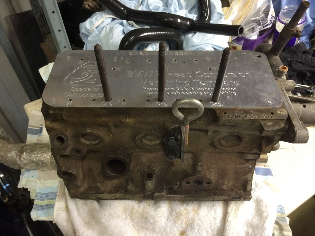
This is the block I will be using:
Bores measure 70.55mm diameter and need to go up a size.
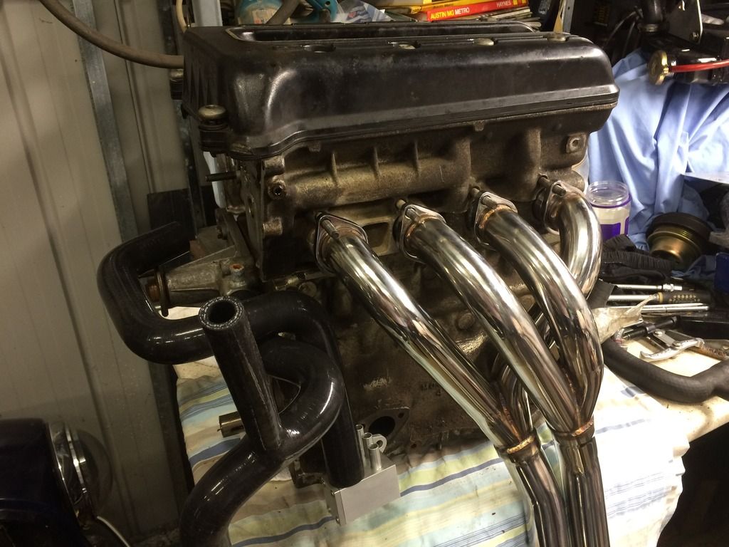
I threw some of the bits on the block. Can't put the cam sprocket end plate on because I haven't cut off the stud for the chain guide in the head.
UK forums say these special hoses aren't that special and need to be modified to work. I think they are right as it looks like one will rest against the exhaust if not modified.
Then I compared the BMW head gasket to the block and a BK450 gasket.
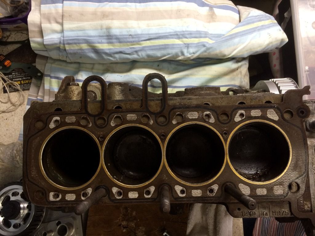
Outer cylinder alignment (yes I have greased my bores, I like them greased):
Inner cylinder alignment:
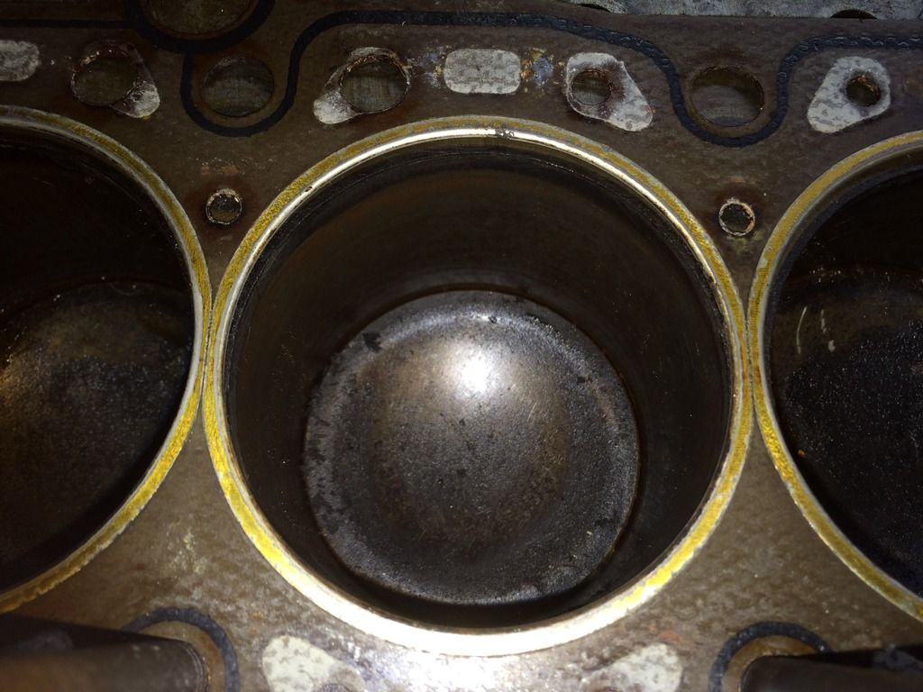
Things I noticed:
The BMW block is an open deck and the BMW head has symmetrical water passages for each cylinder. It is the holes in the head gasket that control the flow of the water from block to head. There is a pattern to the holes in the gasket that ensures that the water doesn't just short circuit around in the front of the engine. Excluding the three holes near where the cylinders meet, there is only one hole around No. 1 cylinder and 4 holes around all other cylinders. The single hole in #1 is 5mm diameter. The other holes are either 6mm or 10mm. The 10mm holes are on the exhaust side of the head and opposite from the outlet.
This is a strong difference to a mini where the water passages are no different for cylinder 1 than cylinder 4. The mini does have bigger passages on the back side opposite the pump inlet and the thermostat outlet to encourage the water around the back of the engine.
So, with BMW having obviously thought about this cooling flow issue it was surprising to see that the drilling guide from SC recommending that all water jacket holes drilled in the block be 5mm. I think some more investigation is needed on this one.
Onto the holes in the block. The SC book commits precisely 1 short paragraph in its 60 pages to this fundamental step.

It helpfully suggests to "drill and tap the hole out to allow a steel insert to be thread locked in place". Not much to go on me thinks.
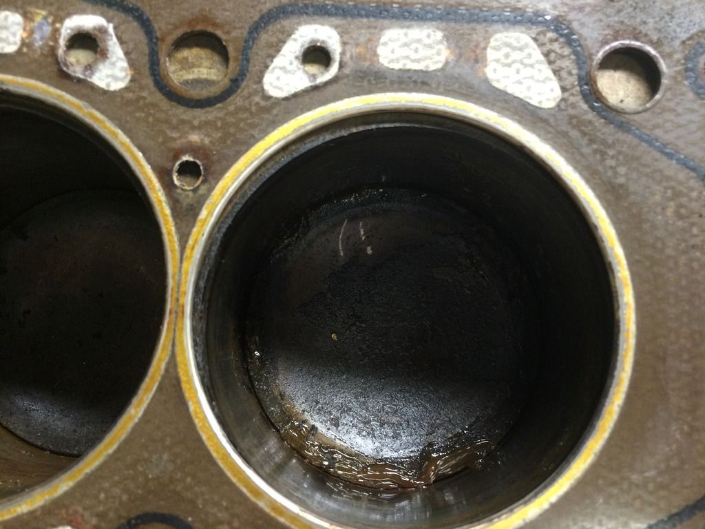
I see 4 different diameter holes, three if you exclude the existing stud holes that are already tapped. They are:
Use -- Approx diameter Studs -- 9.9mm
Water -- 6.3mm <--- the build guide says that the 8 of these at the engine number side of the block can be left un-plugged but all the photos show them plugged.
Push rod -- 10.2mm
water -- 12.5mm
I guess they could have said what diameter drill, how deep to drill (the deck appears to be about 13mm thick to the water jacket) and what size tap to use but that would be too easy.
I read on the UK forums that people recommend using threaded cast iron rod so that the drill holes that overlap the existing holes don't get drill wander due to the different strength materials. I see from old pics on here that most of the holes are filled with set screws. I would like to know if it is worth the effort to get rod and get it threaded to the 4 different sizes required or are simple low strength grade screws satisfactory?
I know Matt Read will know these answers but I'd like to find out and put them in here for completeness. There is fly cutting pistons and sealing up the head to do for this conversion but I think people would agree that the block modifications are the most intimidating part of this build. They are too poorly described in the SC book for the money.
While I'm on this little rant here are the other elements not properly described in the SC book:
1) Oil passage in the head. Where to drill and where to block if you don't want the external line
2) Oil feed to the head. The 'jackshaft' that you can buy from SC is modified to allow increased oil flow to the head. Ok, but if I want to use the camshaft I have, will I get enough oil to all those cam shaft bearings? What can I do to my cam to make sure I do?
3) The alloy timing plate that goes on the front of the engine has a big hole for the mini's cam. There is another alloy piece that goes in this hole and has the shaft seal in it and an o-ring around the outside. I assume that the steel mini camshaft restraining plate (three holes for screws and one to let oil out) is used between these two. It could be left out but then there doesn't appear to be anything stopping the cam walking out of the block.

4) The crank pulley is moved out towards the radiator by this conversion. SC will know how much by and could say so we know how much we have to move the water pump pulley and the alternator by to match but no, we have to work it out ourselves.
I'm sure there are other things that will crop up but these are the ones that stand out in the first 5 minutes.
Of course none of this is rocket surgery and I will get through and over it but If this is your business to publish a how-to guide, then you want to do a better job than SC have done.
M


