A milestone has been achieved (finally). I have quite distracted since October since so many friends have been getting married, and too many friends and family have been wanting their cars serviced or repaired. The last one left the garage this morning and have said no more until I get a solid few weeks of Mini work.
I have made slow progress on the subframe and as of today, have completed the engine mounts

So this is what's been happening in the last 3 months...
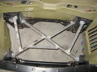
The front brace bar (this is before the valance was fitted to the shell) was fabricated.
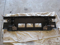
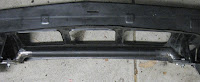
As usual, the front of original subframe was cut away and a frame was tacked together to enforce the subframe position.
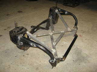
Spars (using 32mm OD tube w/ 3mm wall thickness) have been bent up and welded in place, ensuring that the drivers' side spar did not foul against any pulleys or future belts.
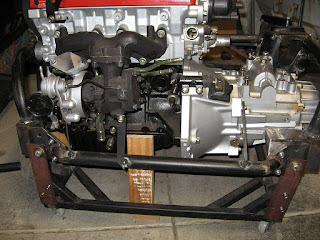
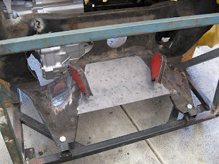
The engine was positioned in the engine bay (with subframe fitted) and I measured some key distances from the engine to subframe. Those measurements were then replicated with the subframe and engine in the JIG and then the engine was bolted/welded in place using some steel bar front & back with wood holding the CV cups up as well.
One bar on either side of the turbo and one on the gearbox
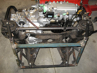
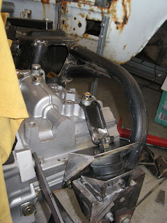
One bar on the gearbox, one on the intake manifold and one on the equaliser driveshaft bracket (if you look carefully)
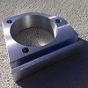
Now here is the major difference in my subframe compared to those done so far. I am using rubber "cotton-reel" type mounts from a V8 Land Rover for the front & side mounts. They are much more compact than the Starlet mounts and given they are designed for a V8, they will be more than strong enough for this engine. I put the idea of using these mounts past my engineer and he saw no problem with it.
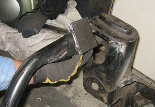
This was my first attempt - mounted at a 45 degree angles, but then after talking to a local Land Rover workshop, I relalised the correct angle used in the V8's is 30 degrees, but I don't have a pic of the correct one.
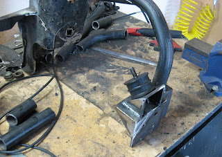
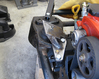
The side mount was was made from some shaped steel plate (all plate used was 6mm) contoured around the spars.
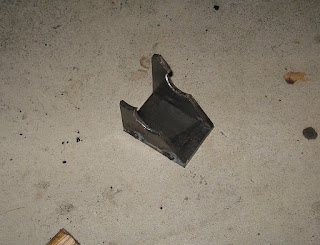
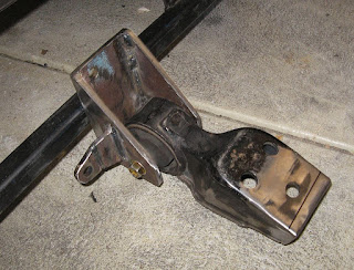
The side engine mount bracket ended up looking like this. Due to the position of one of the bolts, I had to cut away the corner of the angled plate and weld in section of tube so that the bolt could still be used.
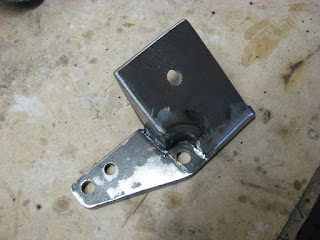
The front engine mount used not only a custom section, but the brace that was used in the original Starlet mount was cut and re-welded to bolt to the custom bracket with a blind nut, so that it provides some additonal support between the bracket and the top of the gearbox.
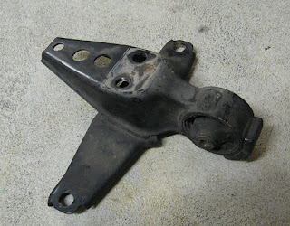
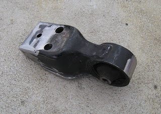
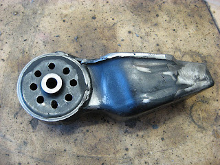
Using a Land Rover V8 mount for the rear engine mount was going to make fitting the engine a bit tricky due to the bolts cast in the rubber mount all pointing inward, so I decided to use the Starlet mount and have the rubber (which was cracked and perished anyway) recast in Polyurethane.
I trimmed down the stock mount.
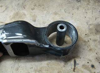
cut off the "wings", added some 3mm plate and made a type of box section as well as adding a third bolt hole.
The rubber was badly cracked in the mount so using a chisel and dremel, it was all cut out
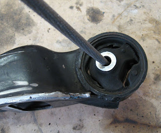
The new polyurethane cast - in Shore 65 hardeness. This is still quite hard for the mount so as per suggesstion of the casting company, I drilled a series of 8mm holes to provide some further flexibility
So to figure out where to bolt this, some 5mm plate was cut to fit between the wings for the mount to bolt to (only tack welded for now)
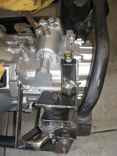
The mount was clamped into the final position, which gave enough clearance to the to the engine bracket (you can see the single piece of plate bolted to the rear of the gearbox in this pic). The remainder of the bracket was measured and built around the position of the clamped mount
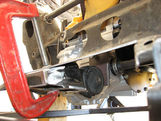
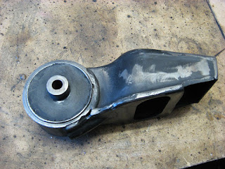
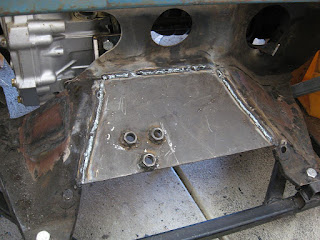
The final design
I marked, drilled some holes, welded some M12 nuts in place and that's that. The engine can now sit freestanding
_________________
-Alan
I blame my dad for my love of minis. I think I was conceived in the back seat of one
I also blame my Dad for me being 6' 1" - not really the optimum height for driving a Mini.